Version 2.0
Adding a turbocharger system to a car that was not designed for it is not a simple process. Like most things in life, you get out of it what you put in. There are many paths to turbocharging your car. You can use the best parts money can buy or you can use junkyard parts. How much forethought and work you put into your setup is directly proportional to how much performance and reliability you will get out of it. To many times I have heard people complain about how poorly their system performed, or how turbo Hondas are unreliable. If done correctly a turbo Honda can be just as reliable as a naturally aspirated or stock turbocharged car. The key is research, planning, and preparation of the vehicle.
An excellent source of information is the book "Maximum Boost: Design, Testing, and Installing Turbocharger Systems" by Corkey Bell. Though not specific to Hondas, this book is one of the best sources for general information on what is required to design a turbocharger system.
This FAQ does not cover supercharging because at the time of this guide's writing there are no kits available for the 1990-1993 Integra. The Jackson Racing SC does not clear the fire wall on the 90-93 Integra, there is also an issue with brake master cylinder clearance. Vortech does offer kits for the 99+ B16 Civic Si and 94+ Integra. One G2IC member was successful in modifying one of these systems to work with his car. The relevant information can be found here:
http://www.g2ic.com/forums/showthread.php?s=&threadid=16023&highlight=vortech
Information on an attempted Jackson SC install can be found here:
http://www.g2ic.com/forums/showthread.php?s=&threadid=71624
The mechanics of a turbocharger are closely related to the mechanics of a jet
engine. If you were to modify the turbo so that the compressor outlet fed the turbine inlet you would be on your
way to making a jet engine (junkyardjet.com). A turbo's relationship with a jet engine should
give you some idea of the potential of turbochargers. A turbocharger harnesses
the wasted energy of exhaust gases exiting the engine to spin a turbine that
compresses the intake air charge.
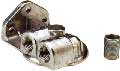
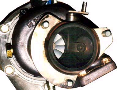
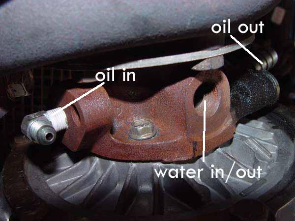
Exhaust gases are directed into the turbocharger through the square inlet in the exhaust housing of the turbo (shown in the bottom left of the above picture). The exhaust flows through the exhaust housing spinning the exhaust turbine. After going through the exhaust housing, the gasses flow out through the exhaust housing outlet(middle left in the picture). The turbine is connected to the compressor wheel on the intake side of the turbo through the center bearing housing. The center housing will have ports for oil to flow in to and out of to lubricate and cool the shaft, and it may or may not have ports for water to go in to and out of. The above picture does not show ports for water. Fresh air is brought into the turbocharger through the air inlet (middle right in the picture). The air is compressed by he compressor and the now pressurized air flows out through the compressor housing. Note:The picture above shows a turbocharger with an internal wastegate.
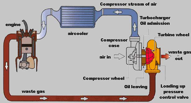
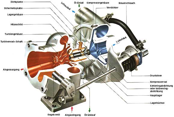
Above we see the basic layout of the components of a turbocharger system. Exhaust gases leave the engine via a turbo manifold, this replaces the stock exhaust manifold or header. One thing missing from the above diagram is an external wastegate. The wastegate is used to control boost levels by allowing exhaust gasses to bypass the turbo, thereby decreasing the volume of exhaust available to spin the turbo's turbine. In a turbo Honda, the turbocharger is bolted directly to the manifold. After moving through the turbo, exhaust gasses exit the turbo through a downpipe which connects to the rest of the exhaust system. Fresh air ,after being compressed by the turbo, passes through some intake piping and into an intercooler ('aircooler' in the above diagram). An intercooler works exactly like a radiator except pressurized air passes through it instead of water. The intercooler is mounted on the front of the car so air flows through it as the car moves down the road. This cools the pressurized intake air charge. This is necessary because when air is pressurized it heats up. Another component missing in the above diagram is a blow off valve (BOV). The blow off valve vents pressurized air when the throttle plate is closed. This prevents a pressure surge from building up in the system and possibly damaging the compressor wheel and the turbo's bearings. Another component not shown is a pop off valve (POV). Often not used on turbo Hondas, a POV is a safety valve that opens, and stays open until manually closed, when a preset boost level is reached, venting most if not all pressurized air. This prevents an overboost situation that may occur if there is a wastegate or boost controller failure.
It is very important to establish a realistic goal early in the project. You should consider your budget and also determine a target horsepower. Do not base your goals on a certain PSI. PSI is not a valid consideration because the turbo determines what PSI will result in what level of power. For instance 10psi on a tiny T25 turbo will not produce nearly the amount of power that a huge diesel semi truck turbo will at 10psi. A small turbo will produce less volume of air flow, and therefore less power, at a given PSI than a large turbo. Also keep in mind that generally the higher your horsepower goal is, the more money it will take to reach that goal. Be realistic when setting the horsepower goal, 300 horsepower in a front wheel drive Honda is A LOT of power for the street. It is a good idea to keep in mind such things as fuel consumption and wheel spin when setting your goal. Many people setting out on the forced inducting path throw around horsepower numbers without much knowledge about just how much power it is and how the car will react to it.
Back to TopThere are many decisions that need to be made when adding a turbocharger to an engine that was not designed for one. These options include whether or not to go with a stock motor or a motor rebuilt with aftermarket parts. Whether to run the non-VTEC LS, VTEC, or LS-VTEC motor is another, often controversial, decision that needs to be made. Realize that an entire guide can be written on this topic, as such, no attempt was made to make this section exhaustive. This section will present the advantages and disadvantages of the most popular motors and whether or not to rebuild them with aftermarket parts or leave them stock.
B18A/B
The B18A/B is an excellent engine
to turbocharge especially since it is the engine most 90-93 Integras come with.
The long stroke enables the B18A/B, AKA LS motor (although they were available
in the RS, LS, and GS trim models), to put down impressive torque numbers, specifically
top end torque. The stock compression ratio, at 9.2:1, is also ideal for boost.
All things being equal, at a given horsepower, the LS motor will put down more
torque than a VTEC counterpart, however the LS motor will require more boost
to get to that given horsepower. The horsepower to torque differential, on average,
is 10% in the LS motor (stock stroke and displacement) and 20% in the VTEC equipped
counterpart. This motor is particularly reliable as well. Stock LS motors have
been boosted to 300hp with proper fuel / engine management. Boosting at these
levels requires precise tuning as the slightest bit of detonation can lead to
terminal engine failure. Built LS motors have seen 500+ horsepower.
B17
The B17, which came in the 92-93
GSR, is a VTEC motor which has some characteristics that need to be addressed
when turbocharging. The 9.7:1 compression ratio must be kept in mind when tuning
the car. With the higher compression ratio less boost will be required to reach
a horsepower goal than it would with a lower compression engine. Also, due to
the VTEC system, cam timing on the B17 raises some issues that need attention.
The valve overlap, intake and exhaust valves open at the same time, can lead
to exhaust gas reversion issues. Reversion occurs during valve overlap and exhaust
gasses are drawn back into the cylinder. Obviously this is not a good thing
when you are forcing an already hot, pressurized intake charge into the cylinder.
It can lead to detonation and generally poor performance. Fortunately with the
use of adjustable cam gears the overlap can be tuned out. B17, and all other
VTEC motors, will put out more horsepower with less boost than a non-VTEC motor,
about 14% on average. Stock B17s have seen 300hp while built motors have seen
500+ horsepower.
B16
The B16 is a very common swap into
90-93 Integras. As with the B17, the motor has some characteristics that need
to be addressed when turbocharging. The 10.1:1 or 10.4:1 compression ratio must
be kept in mind when tuning the car. With the higher compression ratio, less
boost will be required to reach a horsepower goal than it would with a lower
compression engine. Also, due to the VTEC system, cam timing on the B16 raises
some issues that need attention. The valve overlap, intake and exhaust valves
open at the same time, can lead to exhaust gasses reversion issues. Reversion
occurs during valve overlap and exhaust gasses are drawn back into the cylinder.
Obviously this is not a good thing when you are forcing an already hot, pressurized
intake charge into the cylinder. It can lead to detonation and generally poor
performance. Fortunately with the use of adjustable cam gears the overlap can
be tuned out. B16, and all other VTEC motors, will put out more horsepower with
less boost than a non-VTEC motor, about 14% on average. Stock B16s have seen
300hp while built motors have seen 500+ horsepower.
B18C
The B18C is not a very common swap into the 90-93 Integra. However the larger displacement over the B16 does have advantages. As with the other VTEC motors, the B18C has some characteristics that need to be addressed when turbocharging. The 10.1:1 compression ratio must be kept in mind when tuning the car. With the higher compression ratio, less boost will be required to reach a horsepower goal than it would with a lower compression engine. Also, due to the VTEC system, cam timing on the B18C raises some issues that need attention. The valve overlap, intake and exhaust valves open at the same time, can lead to exhaust gasses reversion issues. Reversion occurs during valve overlap and exhaust gasses are drawn back into the cylinder. Obviously this is not a good thing when you are forcing an already hot, pressurized intake charge into the cylinder. It can lead to detonation and generally poor performance. Fortunately with the use of adjustable cam gears the overlap can be tuned out. B18C, and all other VTEC motors, will put out more horsepower with less boost than a non-VTEC motor, about 14% on average. Stock B18Cs have seen 300hp while built motors have seen 500+ horsepower.
B20
The B20 motor is a direct replacement
for the B18A/B. The only advantage of the B20 over the LS motor is the extra
two tenths of a liter displacement. This extra displacement comes at a price
however. In order to achieve 2.0 liters of displacement the cylinder sleeves
are manufactured at 84mm instead of the 81mm on other B series sleeves. The
design of these sleeves varies slightly from other Honda sleeves which accounts
for their cracking more easily. A simpler way to achieve the 2.0 liters of displacement
is to resleeve a LS motor and bore it to 84mm. Also consider that the B20 is
much harder to find, which can make them considerably more expensive than a
LS motor. B20 compression ratios are 8.8:1, 9.2:1, or 9.6:1 depending on year.
LS/VTEC
A turbocharged LS/VTEC is a very
potent motor. However it is also the hardest to build so that it runs reliably.
The LS/VTEC gives the best that the LS and VTEC motors have to offer, the high
horsepower from the VTEC and the high torque of the LS. By using the LS block
and a B16 head (with a stock bottom end) a compression ratio close to 9.0:1
is attained. If rebuilding the motor, the block can be resleeved with aftermarket
sleeves and bored to 84mm resulting in 2.0 liters of displacement. A reliable
LS/VTEC motor is very difficult to build, as such it should only be attempted
by an engine builder experienced with building LS/VTEC motors. Since building
a good LS/VTEC motor is such an art, engine builders charge a premium for their
services. Also keep in mind that the bottom end of a LS motor was not designed
to rev up to the level where the VTEC motors are meant to shine.
Stock
Most stock Honda motors take boost quite well (the B20 being the exception). But before hastily slapping a turbo on your +150,000 mile engine, the health of the engine should be considered. A simple compression and leak down test should be performed to determine if the engine will last when subjected to boost. Any mechanical deficiencies will be amplified when boost is entered into the equation. If the compression pounds per square inch is significantly below 200psi, the differential between cylinders is more than 10%, and/or the leak down test shows a 10% or greater loss, the cause of the loss should be investigated and remedied.
Prior to installing the turbo it is a good idea to replace the water pump, oil pump, thermostat, etc if they have not been replaced recently. Preparation is key in creating a reliable turbocharged engine.
BuiltHonda motors built with aftermarket parts can be boosted more safely and to higher levels than those motors with stock bottom ends. The parts needed when building a motor for use with a turbocharger include connecting rods (Crower and Golden Eagle being most popular) and pistons (JE/SRP and Arias) with a balanced Honda crankshaft. With new pistons, a decision about compression ratios must be made. The most popular ratio is 9.0:1. Higher ratios can be used but be aware that the higher you go the more critical precise tuning becomes. With the higher compression ratio a lower amount of boost can be used to attain a horsepower goal. One advantage to a higher compression ratio is better low end, off boost, power and response.
Since Honda motors use a floating cylinder design, stabilizing and strengthening the cylinder sleeves is of some concern. The two options for doing this are aftermarket sleeves (Golden Eagle, Benson's) and blockguards (Golden Eagle, NuFormz, STR). Aftermarket sleeves are thicker than stock sleeves and are also designed to resist walking, moving from side to side, in the water jacket which can compromise the seal between the head and block resulting in a blown head gasket The new sleeves are pressed into the block by a machine shop. One downside to aftermarket sleeves is that if the machine shop does not properly press the sleeves in, they will not seal well with the headgasket and head. Another concern is that over time the sleeves may sink which results in the same loss of seal. Blockguards fit into the water jacket that surrounds the cylinders preventing them from walking. Block guards need to be pressed into the water jacket by a machine shop. One disadvantage to the block guards is that since water flow near the top of the cylinder is restricted by the guard, a hot spot on the cylinder wall develops. This hot spot in the cylinder wall expands the cylinder wall which can lead to a breached seal between the block and head.
Some modification to the head should also be considered. The standard port and polish is a good idea as is port matching to the intake and turbo manifolds. Of particular importance are stainless steel valves. Stainless steel valves (Crower) are more resistant to heat fatigue and the associated deformation than stock valves. This will help to prevent burned valves. Aftermarket cams that are designed to be used on normally aspirated engines should not be used, stock cams work quite well with turbochargers. A few companies are making aftermarket turbo cams however at the time of the writing of this guide no results of using these cams could be found.
Back to TopExhaust gases leave the engine via a turbo manifold, this replaces the stock exhaust manifold or header. Turbochargers operate on heat and exhaust gas velocity characteristics. A good turbo manifold will maintain these characteristics by material choice and design. Material choice can influence heat retention due to how certain materials react to heat. The two most common materials are cast iron and stainless steel. Cast iron is the material used in log type manifold like those made by Revhard and Drag. This material offers good heat retention and is cheap but can be difficult to weld. Stainless steel is used on most tubular manifolds and in Inline Pro cast manifolds. Stainless steel retains heat better than cast iron but it is also more expensive. Manifold design is very critical for efficient heat retention and gas flow. Material thickness plays a large role in heat retention, as does surface area. In order to retain the most heat the ideal manifold will have the thickest material plausible and the least amount of surface area. The thick material will help insult heat and the reduced surface area will reduce heat loss through radiation. Heat retention also plays a part in keeping exhaust gas velocity high. Another key to keep gas velocity high is manifold runner diameter. Diameters should be small to keep the gases moving at their maximum speed, but not so small that they create back pressure or choke gas flow at high RPMs. Wastegate port placement is also very important. Wastegate placement should be such that exhaust gasses can be vented from all four cylinders equally, not from just one or two runners. Wastegate placement should also allow for the exhaust gasses to flow into the wastegate by changing direction as little as possible.
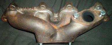
Log Type (cast) Manifolds: Cast iron manifolds are a great match for street performance. They are more crack resistant than tubular manifolds because they are one solid piece. They also take up less room and are cheaper than tubular manifolds. Most cast manifolds also allow for power steering and air conditioning. Some performance is sacrificed with a cast manifold compared to tubular manifolds, but not much. One disadvantage to many, but not all, cast manifolds is poor wastegate port placement as is demonstrated in the pictures below.
|
Bad: As you can see on this Drag manifold the wastegate port is only on one runner. Only exhaust from the #1 cylinder will flow through the wastegate. |
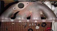
Better: On this Rev Hard manifold the port is on the #2 cylinder. Exhaust from the #1 and #2 cylinders will go through the wastegate. Thanks to cjsls from G2IC for the picture. |
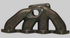
Best: This is the Inline Pro manifold. As you can see the port is positioned directly above the collector. Exhaust gas from all cylinders can go through the wastegate. |
Tubular Equal Length Manifolds: For all out performance a tubular manifold is the only option. The runner length of these manifolds is made equal so that the exhaust pulses from each cylinder do not interfere with each other as they enter the turbine housing. This makes the most efficient use of the energy in the exhaust gases possible. The results are quicker spool up and better all around performance. How ever there are some disadvantages to tubular manifolds. Because of the equal length primaries the amount of surface area to radiate heat is a lot larger than with a cast manifolds. Also because of the way these manifolds are made, with segments of pipe welded together, variances in the consistency of the material promote cracking. Also keep in mind that the welds will be stressed with each heat cycle which also promotes cracks. One way to minimize the chance of cracking is to support the weight of the turbo with a bracket that bolts to the block. One advantage worth pointing out is that since these manifolds are handmade and not mass produced from a mold like the cast manifolds it is much easier to get manifolds with turbo flanges for turbos other than the Garrett T3 and flanges for various wastegates. Also be aware that using a tubular manifold may take up a bit more space and require that a Civic 'Half Length' radiator be used instead of the full size Integra radiator.
Notable tubular manifolds include those made by Full Race, Rev Hard, South Florida Performance (SPF), and Love Fab, these are all quality manifolds. Those manifolds made by SS Autochrome, usually sold on ebay.com, are very well known for cracking, they should be avoided.
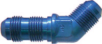
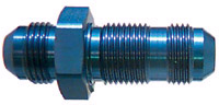
If you have decided to use a Mitsubishi 14B or T25 turbo you have a couple manifold options. One option is to have the Garrett T3 flange removed from a manifold and have a flange for the 14B or T25 welded on. Of course this is only an option on tubular manifolds. Another option is to use an adapter, which bolts to the manifold with the Garrett T3 flange and the turbo bolts to the adapter. One disadvantage of the adapter rout is that instead of one join between the manifold and turbo there are two. Each joint has the possibility of leaking. If there is a leak pre-turbo the turbo will not perform to its full potential. Contact Forced Performance for 14B and T25 flanges and The Drop Shop for adapters.
Keep in mind that all B series manifolds are interchangeable. A manifold that fits a B16 will fit a B18 and vice versa. However just because it fits the head does not mean that once a turbo is attached that it will fit. All manifolds position the turbo slightly different in relation to the engine block, air conditioning and power steering components, and crossmember. Many times you may find that once the turbo is bolted up to the manifold the turbo will interfere with the block, requiring the webbing on the block to be ground down (shaved) to allow the turbo and manifold to be fully mounted on the head. Also because of these positioning issues it may be difficult to locate components such as wastegates and downpipes in the best positions.
You cannot modify and use the stock exhaust manifold or an aftermarket header. It will not work, do not try it.
A wastegate is used to control boost levels by allowing exhaust gasses to bypass the turbo, thereby decreasing the volume of exhaust available to spin the turbo's turbine which will limit the amount of boost created by the compressor. The wastegate has an internal spring and diaphragm which boost pushes on, these springs are rated for different psi (or BAR, 1 BAR = 14.5 psi) levels. If you have a 7psi spring (0.48 BAR) boost levels will be maintained at 7psi. Wastegates come with springs pre-installed, choose the wastegate that has the spring that matches the psi you need. One disadvantage of relying on the wastegate spring to regulate boost is the development of a condition called wastegate creep where the wastegate will start to open before it should. As boost gets closer to the set level of the spring, the spring will begin to actuate, opening the wastegate. This increases the time it takes the turbo to make full boost.. A boost controller can be used to prevent this condition. Boost creep is another condition that you need to be aware of. Boost creep occurs when even though the wastegate is open, boost continuous to rise, usually as the engine approaches high RPM. This occurs because the wastegate port is to small, or is in a bad position, and enough exhaust gases cannot bypass the turbo through the wastegate, making boost levels rise. Fortunately this is a rare condition and is not often a problem unless you are making over 500 horsepower.
The most common type of wastegate used on turbo Hondas are those with the the Rayjay type flanges produced by Turbonetics (Deltagate) and Tial. The Deltagate is the cheapest wastegate you can get, and like most cheap parts, you get what you pay for. The Deltagate is very unreliable due to its materials and design. The material used in the diaphragm of this wastegate is very well known for degrading due to the high heat (compounded by each heat cycle) it is exposed to. The compact design of the wastegate lends to the degradation of the diaphragm because it allows heat to transfer easily to the diaphragm. However, because of it's compact design it can be bolted directly to the manifold without the use of an elbow to clear the hood. The Tial wastegate costs a little more than the Deltagate but it is a much better product. A 38mm Tial wastegate is rated for over 400 horsepower and can be bought with many different spring rates. Different springs can also be swapped in. The materials and design are much better than the Deltagate counterpart. Because the body of the Tial wastegate is longer, there is more surface area for heat to radiate from, transmitting less of that heat to the diaphragm. The disadvantage of using the Tial is that it cannot be bolted to most manifolds without the use of an elbow to clear the hood.
Because of the design of the Rayjay flange, wastegate gaskets can burn out and leak quite easily. Contact Cometic for high temperature, metalic replacement gaskets.
A new player in the wastegate market is TurboSmart. The TurboSmart wastegate is very new and not much is known about this wastegate's performance or reliability at the time this guide is written.
One last thing that should be considered is the dump tube for the wastegate. There are 2 options, vent the wastegate to the atmosphere through a short tube or route the wastegate exhaust back into the exhaust system at the downpipe. By venting the wastegate to the atmosphere the car will be a bit louder when the wastegate is open but it keeps the wastegate's exhaust out of the exhaust system which will reduce back pressure. Routing the wastegate exhaust back into the exhaust system will result in a quieter car and a cleaner install. The key to minimizing any disruption to exhaust flow at the point where it dumps into the downpipe is keeping the angle of the merger as shallow as possible, you want the exhaust from the dump tube to change direction as little as possible so it flows easily into the exhaust flow that is in the downpipe. Also locating the merger at least 18" downstream from the turbo will reduce flow disruptions. It is a good idea to use a slip joint between the wastegate and the beginning of the dump tube to allow for the high amount of thermal expansion that occurs when the wastegate opens and exhaust flows through it.
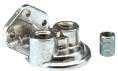
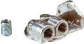
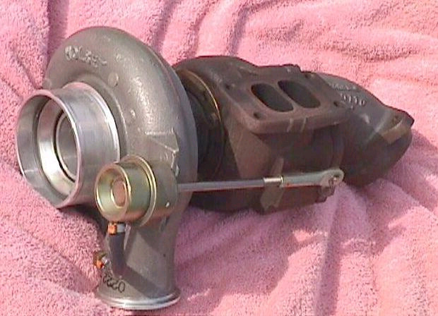
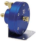
Most all turbochargers found on cars with factory turbochargers have internal wastegates. Internal wastegates work directly on the turbo by way of a butterfly type valve in the turbine housing (as seen in the first picture below). The valve is operated by a actuator located on the compressor housing. The actuator is connected to the valve with a rod (as seen in the second picture below). The actuator pushes on the rod, opening the valve. Since the valve is directly on the turbine housing it is located in an ideal location where it can vent all exhaust gases, not just those coming from one or two manifold runners. Unfortunately the actuator can be quite fragile and is known for breaking. Another disadvantage is the small port size which can lead to boost creep. Also, since the springs cannot be changed in the internal wastegate the level of boost cannot be changed without the use of a boost controller. Some aftermarket companies sell block off plates so that the internal wastegate can be removed and an external wastegate can be added to the system.
Selecting the correct turbocharger can be a complicated task. With all the different options of different A/R ratios, trims, housing sizes etc. there is enough confusion to make your head spin. An entire guide can be written on this topic alone. As such this section will present some of the terms used in describing different turbo options and some of the popular choices of different turbos and their advantages and disadvantages.
A/R Ratio (Area/Radius Ratio) - There is an excellent description of A/R in the Corkey Bell book "Maximum Boost: Design, Testing, and Installing Turbocharger Systems", since I can't think of a better way to define the term I'll copy Mr. Bell's description:
" While basic turbine size reflects a measure of the turbine's flow capability, the A/R ratio is a method of fine tuning between basic sizes. To easily grasp the idea of an A/R ratio, imagine the turbine housing as nothing more than a cone wrapped around a shaft to look like a snail. Unwrap the cone and cut of the small end a short distance from the tip. The hole in the end of the cone is the discharge area. The area of this hole is the 'A' of the A/R ratio. The size of the hole is significant, as it determines the velocity with which exhaust gases exit the turbine scroll and enter the turbine blades. For any given rate of flow, a smaller exit will require that the gases flow faster. Thus, the area of the exit is important in controlling the velocity of the gases as they enter the turbine blades. This velocity has much to do with controlling the actual speed of the turbine. It is necessary to keep in mind that the area of the exit is the controlling factor in the bad side-effect of exhaust gas back pressure and, thus, reversion into the combustion chambers.
The 'R' of the A/R ratio is the distance from the center of the section area in the cone to the center of the turbine shaft. All 'A's divided by their respective 'R's will give the same dividend.
The 'R' also has a strong influence in controlling turbine speed. If one imagines the turbine blade tips will travel about as fast as the gas is moving when it enters the tip area, it is easy to see that a smaller 'R' will impart a higher rotating speed to the turbine."
In short, all other things being equal, the smaller the A/R the less lag there will be, but the turbo may not be able to produce power at higher RPMs. A larger A/R will produce more lag but have a lot of top end power.
Trim - Trim, simply put, is the size of the turbine and compressor wheels. Sometimes trim is expressed with letters or stage numbers but they actually represent a decimal number that can be calculated with these equations:
|
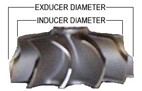 |
All other things being equal the smaller the trim the less lag there will be, but the turbo may not be able to produce power at higher RPMs. A larger trim will produce more lag but have a lot of top end power.
Compressor and Turbine Housings - The size of the compressor and turbine
housings determine what A/R ratios are available and what trim compressor and
turbine wheels will fit. The housings are expressed by codes that are proprietary
to each turbocharger manufacturer and to each product line. For example Garrett
produces a line of turbos with the T, and there new GT, designation i.e. T3
or T4. Mitsubishi calls it's 1990 - 1994 DSM turbo a 14b. Precision
Turbo and Engine uses the SC designation for it's line of turbos. These
designations are arbitrary and have no quantitative meaning.
There are many choices that need to be made when choosing a turbocharger. For your first turbo it is highly recommended that you go with a turbo that has been proven to work with Hondas. Once you get a baseline to work from you will be able to compare your current turbo with one you are contemplating getting in the future. Below are some popular and proven options for turbos.
|
Mitsubishi
Turbochargers
|
||
| Garrett is the industry leader in turbocharger design and production. Garrett has supplied every auto manufacturer with turbos for factory turbocharged cars. Garrett also supplies turbochargers for the dominate Audi R8 Le Mans car and also all CART cars, among others. Turbonetics and Precision Turbo and Engine, supply Garret turbos. The Garrett T3/T04 (T04E, T04B, T04S) turbo is the standard used for Honda applications. This hybrid turbo uses the T31 (commonly referred to as the T3) turbine housing and one of the T04 family of compressor housings. | Precision Turbo and Engine turbochargers are based on Garrett designs. The SC (Sport Compact) lines of turbos use the Garrett T3 turbine housing, and associated turbine wheels, with a T04E compressor housing designed and manufactured by Precision Turbo and Engine. A Precision turbo is a T3/T04E with a redesigned compressor housing. Precision Turbo and Engine turbochargers cost considerably more than standard Garrett turbos. Whether or not that cost is justifiable is debatable since it is unlikely that a street driven car will use these turbo's reworked compressor housing to it's max potential. | Mitsubishi builds some of the best factory turbocharged cars. They also design and manufacture their own turbochargers. The 1990-1994 Mitsubishi Eclipse, Eagle Talon, and Plymouth Laser (AKA DSM) used the 14b turbo. Because these cars came with 2.0 liter engine the 14b is a good match for the 1.8 liter Honda engines. The 14b is a larger turbo than the T25 turbo that was on the 1995-1999 and is a much better turbo in general. |
|
T3 Turbine Housing T04E Compressor Housing T04B Compressor Housing T04S Compressor Housing Most Common Combination The Drag turbo kit comes with a T3/T04B turbo. The T3/T04S with the 60-1 trim is commonly referred to as the 60-1 turbo. It is capable of putting out more power than you will ever need, but with quite a bit of lag. The T25 turbo used in the 1995-1999 DSMs is a Garrett turbo. This turbo has a .45 A/R with a 45 trim turbine and 55 trim compressor wheel. Note that although these numbers are similar to trim numbers in the T3/T04 turbos you cannot compare them since these wheels are in the T25 housings. These wheels are much smaller than the T3/T04 counterparts. The T25 struggles on a turbo Honda at high RPM but does offer good performance at low and midrange RPM. Garrett's new line of turbos with the GT name claim to offer greatly improved aerodynamics and efficiency. Not many people have tried them on Hondas yet so no information could be found. |
All available turbos specs from Precision Turbo and Engine match those available in the Garrett T3/T04E. The SC50 matches the Garrett T3/T04E with .63 A/R and a Stage 3 wheel with a 50 trim compressor wheel, with the Precision T04E compressor housing of course. |
No reliable information could be found on the A/R and trim specs for the 14b turbo. If you have specs please send them to turboguide@beesandgoats.com If you have decided to use a Mitsubishi 14B or T25 turbo you have a couple manifold options. One option is to have the Garrett T3 flange removed from a manifold and having a flange for the 14B/T25 welded on. Of course this is only an option on tubular manifolds. Another option is to use an adapter, which bolts to the manifold with the Garrett T3 flange and the turbo bolts to the adapter. One disadvantage of the adapter rout is that instead of one joint between the manifold and turbo there are two. Each joint has the possibility of leaking. If there is a leak pre-turbo the turbo will not perform to its full potential. Contact Forced Performance for 14B/T25 flanges and The Drop Shop for adapters. For the downpipe you will need the downpipe flange that bolts to the 14b or T25 turbo. These can be purchased at Forced Performance. |
For a list of cars that came from the factory with turbochargers check out:
http://www.g2ic.com/forums/showthread.php?s=&threadid=36403
Use "Junkyard" turbos at your own risk.
Some of these turbos (even some T3/T04 turbos) come with water cooled bearing housings. If you should happen to get a water cooled turbo it's not absolutely necessary that water cooling be used, but it would be a good idea to use it. Water cooling will extend the life of the turbo bearings and seals, reduce the likelihood of coking (discussed in the oil section below), and increase the intervals between oil changes. If you decide to use the water cooling ports, you can run the turbo inline with the heater core or throttle body coolant hoses, these hoses are similar diameters to the turbo coolant ports.
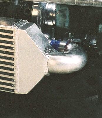
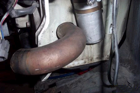
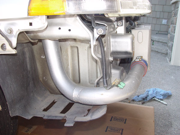
The downpipe connects the turbo's turbine housing to the rest of the exhaust system. The downpipe sees particularly high heat stress which can quickly fatigue and crack the metal. Since downpipe routing is fairly limited due to the placement of the front cross member in the 90-93 Integra the downpipe will generally require a 180* bend directly after the turbo so that the downpipe goes under the turbo and then a 90* bend so it runs back under the car. Because of all these bends 16 gauge, 3" inside diameter pipe should be used to minimize the effect of the bends on exhaust flow. Using 3" pipe can have fitment issues especially if you plan to keep the air conditioning, which we will discuss next, so 2.5" pipe is acceptable to use. Whether or not any horsepower will be lost with 2.5" pipe is debatable (unless you are making about 500 horsepower), but it will take a fraction longer for the turbo to spool with the smaller pipe.
This is the time where you need to decide the orientation of the turbo relative to the car. There are 2 options, either the turbine side of the turbo can be on the driver side or the passenger side of the car. Each has it's advantages and disadvantages. If the turbine housing is on the driver side of the car you may need to use 2.5" pipe to clear the air conditioning compressor (if you want to keep it). With some manifold and turbo combinations it may not be possible at all to keep the AC if the turbine housing is on the driver side. If you chose not to keep the AC then having the turbine housing on the driver side is optimal because you can use 3" pipe and route it with wide radius bends which is best for exhaust flow and minimizes back pressure. This position also allows for optimum placement of an air filter. A disadvantage to this option is that the compressor housing is on the passenger side of the car requiring slightly longer piping to get to the intercooler. The other option is to have the turbine housing on the passenger side of the car. If this option is taken a tight radius bend immediately after exiting the turbo is required. This option will allow the use of the air conditioning compressor without having to worry about the downpipe getting in the way. The disadvantage is that the tight radius bend will impede flow and create back pressure.
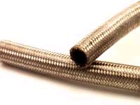
Pre-made downpipes are difficult to come by. With so many different manifold, turbo, engine, car, and turbo positioning options, making downpipes to be bought off the shelf, and be made profitable for manufacturers, would be very difficult. It is for this reason that very few companies sell downpipes. The best option is to have one custom made. Custom made downpipes do not have to be expensive, you can do a lot of the work your self. The first step is to buy mandrel bent pipe, steel braided flex joint, oxygen sensor bung (get 2 and 1 plug, one will be for the OEM oxygen sensor and the other will be for a wide band oxygen sensor for an air fuel ratio gauge that can be used for tuning), and a downpipe flange for the turbo you have. These items can be found at the following places:
|
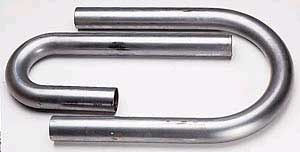 |
Buy several deferent bends, some with tight radiuses, some with long radiuses Next, cut sections out of the various bends so that when they are welded together they will make one continuos pipe. The oxygen sensor should be placed approximately 14" after the turbo so place the bungs there. Add the flex joint to the end of the downpipe where it will connect to the rest of the exhaust system. Once you have cut all the sections of pipe you will need to make you downpipe, mark their position in relation to each other and take the pieces to a welder for welding. You can look in the phone book for a welder. Remember that once the turbine flange has been welded to the downpipe it will deform and no longer be flat. It needs to be resurface flat so that it properly seals with the turbine housing.
If you are not confident in making your own downpipe, most quality speed shops that do turbo installs on imports make custom downpipes. Check around for a good shop that you know has done good downpipes in the past.
One last thing that should be considered is the dump tube for the wastegate. There are 2 options, vent the wastegate to the atmosphere through a short tube or route the wastegate exhaust back into the exhaust system at the downpipe. By venting the wastegate to the atmosphere the car will be a bit louder when the wastegate is open but it keeps the exhaust out of the exhaust system which will reduce back pressure. Routing the wastegate exhaust back into the exhaust system will result in a quieter car and a cleaner install. The key to minimizing any disruption to exhaust flow at the point where it dumps into the downpipe is keeping the angle of the merger as shallow as possible, you want the exhaust from the dump tube to change direction as little as possible so it flows easily into the exhaust flow that is in the downpipe. Also locating the merger at least 18" downstream from the turbo will reduce flow disruptions. It is a good idea to use a slip joint between the wastegate and the beginning of the dump tube to allow for the high amount of thermal expansion that occurs when the wastegate opens and exhaust flows through it.The only option for a prefabricated, bolt-on, exhaust system that is suitable for use on a turbocharged car is from Thermal Research & Development
The catalytic converter is a significant flow restricter in the exhaust system, even presumably 'high flow' cats. You can expect as much as a 30 horsepower gain by removing the cat. Having the cat in the system will also contribute to extremely sluggish low RPM performance. However, removing the cat in most areas of the country is illegal and results in a heavy fine, remove it at your own risk. One option to reduce the chance of being caught it to have a fake heat shield that looks like a cat's heat shield welded onto a straight pipe, making it look like a cat (I'm not telling you to do this, I'm just telling you what some people have done).
Turbocharger wheels spin incredibly fast and are not very sturdy. If a rock, bug, or small animal were to impact the blades of the wheel a catastrophic failure will happen. For that reason, ever effort should be made to use a filter. Many people seem to believe that because of the compressor wheel spinning at such a fast speed a barrier to dirt and grit is created. Nothing could be further from the truth. Turbochargers work like vacuums sucking up anything and everything that gets close to the compressor inlet at a much, much higher rate than a normally aspirated engine does from its intake pipe. Unfortunately, fitting a filter (in an ideal location away from the turbocharger) can be problematic and will require the removal or relocation of some engine bay components in almost every application. If you have chosen to have the turbine housing on the driver side (compressor on passenger side) then you may need to move the radiator fan around to the other side of the radiator, modify the lower radiator hose, and perhaps relocate the battery (highly recommended). Doing this will allow an intake pipe, at the same diameter as the compressor inlet, to be run as far away as possible from the turbo. If you decide to run the turbine housing on the passenger side of the car and have done away with the air conditioning then it is easier to add a filter. If you chose to keep the air conditioning it will be near impossible to add a filter. In the case that you cannot run a filter at least use a fine mesh, such as aluminum screen door mesh which you can find at home depot, and secure it directly onto the compressor housing inlet with a hose clamp.
You will likely have to make your own intake pipe for the same reasons you have to make your own downpipe. To make the intake pipe use the same steps as you did for building the downpipe but use pipe that is the same diameter as the turbo compressor inlet.
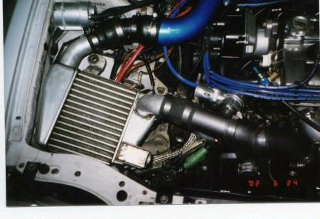
As with all other piping in the turbo system, the intercooler charge pipes will probably need to be custom fabricated. As shown there are many options for pipe routing all dependent on what components you have or don't have. Finding premade intercooler charge pipes that fit your application may be impossible. To fabricate your own pipes follow the directions above for downpipes and air intakes. Pipe couplers (larger diameter silicon hose) can be bought at Baker Precision. Pipe diameters are usually 2" to 2.5". As opposed to exhaust system diameters where bigger is better, here bigger is definitely not better. The larger the pipes are, and the longer the pipes are (plus the larger the intercooler) the more volume the turbo will have to fill with air before it becomes pressurized, creating lag. But there is another side to the coin. If the pipes are to small they can prevent sufficient air volume from reaching the engine even though the turbo is more than capable of providing the required volume. Generally 2.25" is good to about 400 horsepower.
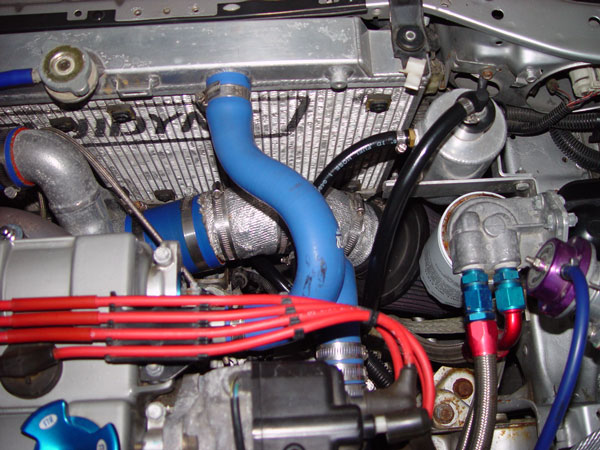
The main problem of routing pipes is the pipe from the turbo to the intercooler. The pipe going from the intercooler to the throttlebody is simply routed the same as a cold air intake (through the space behind the bumper where the resonator was and through the hole that the OEM filter box connected to the resonator). There are many choices for pipe routing all dependent on what turbo you have, how you've positioned it, whether or not you chose to keep the air conditioning, what radiator you use, if you have the windshield washer fluid reservoir, or whether or not you've relocated the battery (highly recommended). As mentioned above the ideal routing will be short to reduce volume and it will also have long radius bends so as to not disrupt air flow. Below are some pictures of some ways the piping can be routed.
  |
This is a very good option for keeping the pipe length short. However some sacrifices had to be made with the radius of the bends. Another downside is that to use this option the the Civic "Half Length" radiator must be used which may raise coolant temps (see the section on Cooling for more information).
Thanks to Race Inc from G2IC for the picture. |
|
Here a hole was cut through the frame to access the area behind the bumper where the windshield washer fluid reservoir was. The bend radius here is nice and long but the sacrifice was pipe length. The metal that had to be cut here is quite thick making it some what difficult to make a clean hole. When ever cutting sheet metal on your car be sure to use some touch up paint on the exposed bare metal. Thanks to LsTurbo91 from honda-tech.com for the picture. |
  |
  |
Here the hole for the windshield washer fluid reservoir is used to run the pipe through. Long radius bends can be used but pipe length is sacrificed. No cutting is required. Though not in this application, the AC compressor could be retained with this pipe routing. |
| Another option, though probably the worse, is to run all pipes to the passenger side of the car and use the same hole (resonator hole) for both pipes. The intercooler inlet pipe would be run along the top of the intercooler to get it to the driver side of the intercooler. The intercooler outlet pipe would be routed as normal. This routing would require absurdly long pipe lengths. This pipe routing was used on the first generation Drag turbo kits. | No pictures could be found. If you have a picture please send it to turboguide@beesandgoats.com |
The key to efficient intercooling is the size and shape of the intercooler. Obviously a larger intercooler will do a better job than a small intercooler but the shape of one intercooler can have an advantage over another intercooler of the same size (volume) but of a different shape. Intercoolers can be had in different width, lengths, and heights. It is best to chose an intercooler that will take up the entire space available for the intercooler and offer the maximum frontal area. An intercooler with more rows, instead of longer rows, should be considered when looking at similar size models. This is because most of the cooling performed by the intercooler is done in the first 50% of the length of the core. Also longer cores can contribute to pressure loss. Getting an intercooler that is thicker compared to another model should be avoided because the ambient air flowing through the intercooler heats up the further it flows through the core, decreasing its ability to cool the air charge the further it flows through the core. By the time the air has gone through half of the core it's capacity to absorb more heat is greatly reduced. Adding more thickness to the core will provide a lot less cooling ability than adding more frontal surface area.
Another intercooling option is to use a side mount intercooler (SMIC) from a 90-99 DSM. These intercoolers are small and can be mounted in the engine bay. This option is far from ideal because of the limited flow the intercooler will receive and from also being in the already hot engine bay. The below picture shows one mounting option that could be quite efficient if a scoop and duct running through the hole for the intake resonator was mounted under the car to direct air through the intercooler.
 Thanks to nosintegra92 from G2IC for this picture.
The last, and perhaps least popular, option is to use an air to water intercooler. Think of an air to water intercooler as an enclosed box with a normal air to air intercooler in it but instead of air flowing through the intercooler fins, water does. Water is a much better conductor of heat than air is. The air to water intercooler is much more efficient than an air to air intercooler, especially at low speeds. The disadvantage is that it requires a lot of extra equipment. The equipment required for an air to water intercooler include: air to water intercooler, water reservoir, water lines, water pump, and water cooler (radiator). It is very difficult to find space for all the extra equipment in a Honda engine bay, especially in a 90-93 Integra if you haven't relocated the battery (highly recommended). Water to air intercoolers are great for the track. You can poor ice water into the intercooler and get extremely cold intake charge temps. For street applications water to air intercoolers are hard to justify. For universal water to air intercoolers check out Spearco.
It is hard to distinguish differences between intercoolers from different manufacturers. Yes some intercoolers from some manufacturers will be more efficient than others or create less pressure drop but you would be hard pressed to notice these differences on a street car. Go with the manufacturer that offers the size and finish intercooler you want at the lowest price. Spearco, Greddy, HKS, and Precision Turbo and Engine all make quality intercoolers.
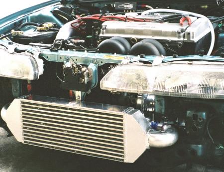
Fitting the intercooler to the front of the car can present some challenges. In all cases, either the bumper cover or bumper support, sometimes both, will need to be trimmed to fit the intercooler. Because the 92-93 bumper is easier to work with, and offers a bigger unobstructed opening, people with the 90-91 Integras frequently convert to the 92-93 bumper. To do this you'll need the bumper brackets, bumper support, bumper cover, and corner lights for the 92-93 bumper. The bumper brackets will bolt up to the same spot the 90-91 supports were. The easiest way to trim the bumper support is to remove the support from the bumper and bolt the support to the car. Next, determine where the intercooler will go and mark where the support interferes with the intercooler. Remove the support and use a cut off wheel to trim the support as shown in the picture below. If you have to cut off so much of the support that it is significantly weakened, you can weld a metal rod (rebar, etc..) to the support to give it strength. The intercooler can be mounted to the car by welding 'L' brackets on the intercooler and then bolting the intercooler to the center hood latch support.


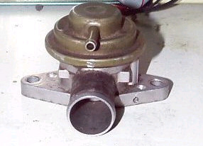
A blow off valve is nothing more than a pressure relief valve. The valve opens when vacuum from the intake manifold acts on the diaphragm. If the pressure surge is not vented off it can cause damage to the compressor blades and turbo shaft bearing. The blow off valves from Greddy, HKS, Apex-i, and Blitz are all quality units. Their only differences are in size, shape, and sound. Some blow off valves have an adjusting screw than can be used to increase or decrease the amount of vacuum required to open the valve.
Those looking for a cheap blow off valve can use the one from the 90-94 DSMs. This blow off valve is very similar to the Greddy Type S valve. Some people prefer to 'crush' the blow off valve in a vice to increase the spring rate to reduce the likelihood of leaks. The picture below shows a crushed 1G DSM blow off valve, note that the top section is slightly depressed into the middle section of the actuator, this is result of the crushing. The flange for the 1G DSM blow off valve can be found at Road Race Engineering
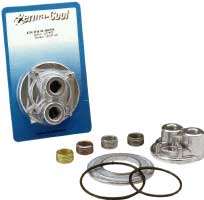
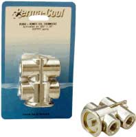
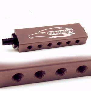
The blow off valve, wastegate, fuel pressure regulator(s), and boost gauge all require connections to vacuum lines to operate. For most components the stock diameter vacuum hose and 'T' fittings are sufficient. Hose and fittings should be available at your local car parts store. If you are running a B18A intake manifold you'll find some very handy ports on the back on the driver side of the manifold. These are perfect for running the blow off valve, fuel pressure regulator(s), and boost gauge. If you have a different intake manifold and need more ports you can use a vacuum manifold like that sold by Golden Eagle. This allows you to create many many vacuum sources from one large vacuum source. You can also find vacuum manifolds at McMaster on page 162 of their catalog.
Below are some pictures of the vacuum line routing for these devices.
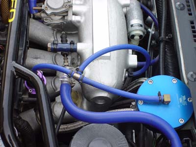
For the wastegate, you will want to use slightly larger diameter hose. For the wastegate you will need a vacuum source that is close to the turbocharger, some turbos even have a fitting on the compressor outlet for a barbed fitting for the vacuum source. It is important to keep vacuum lines for the wastegate as short as possible. If the lines are to long they can delay the speed at which the wastegate will operate, not a good thing when regulating boost. If you are using a boost controller to regulate the wastegate then these vacuum lines should also be kept short. Below is a picture of the vacuum routing for the wastegate with a boost controller.
If you find that the vacuum lines are coming off of fittings (pushed off the fittings from boost pressure) you can use zip ties as small hose clamps to keep the hoses on their fittings.
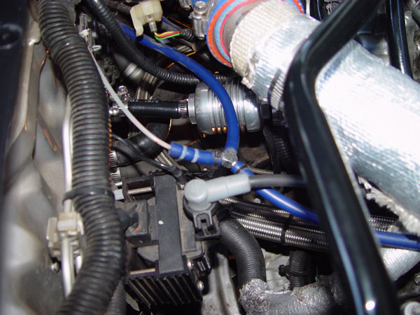
Turbochargers need oil to lubricate and cool the bearings. Failure to provide adequate oiling for the turbo can result in a condition called coking (pronounced with a long O as in Coke). Coking occurs from high heat breaking down the oil (even synthetic) molecules which will create a build up of sludge that sticks on turbo shafts and bearings. Coking will begin to occur when oil reaches about 230* F for conventional oil, 270* for synthetic oil. This can be of real concern if the turbo is run hard for a long period of time and then the engine is turned off, allowing oil to sit on the extremely hot turbo shaft. A turbo timer can be used to avoid this situation.
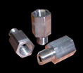
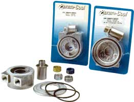
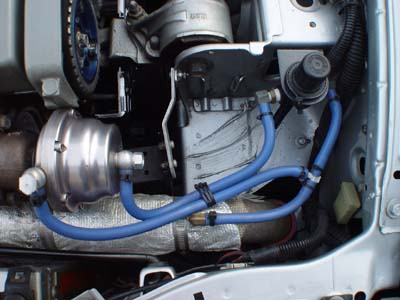
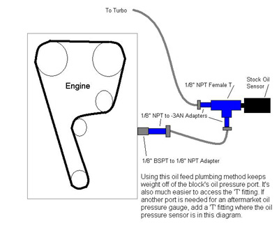
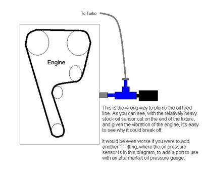
For the oil supply, a 'T' fitting is used where the oil pressure sensor port is on the back of the block near the oil filter. The 'T' fitting is required so that the oil pressure sensor can be reinstalled (although you don't have to reinstall it). The best way to install the supply line is with a short length of hose between the oil pressure port and the 'T' fitting. If the 'T' fitting is installed directly to the block, and then the stock oil pressure sensor on the end of that, you end up with quite a bit of weight on the end of a long, skinny, hallow pipe that can, and will, easily break because of the vibration of the engine. By using a short length of hose between the oil pressure port and the 'T' fitting, the 'T' fitting can be remote mounted removing all that weight from the port, it will also be a bit more accessible. The parts required for the oil supply line include:
|
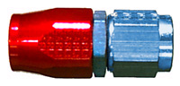
2 lengths of -3AN steel braided hose with -3AN hose end fittings. One length should be shorter than the other. You can get these lengths cut to your specs at just about any serious local speed shop.
|
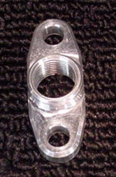
1 1/8" BSPT to 1/8" NPT Adapter This fitting goes into the port in the back of the block (BSPT side first), this item can be found at http://www.z10eng.com/
|
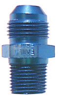
4 1/8" NPT to -3AN Adapters One of these will go in the BSPT to NPT adapter, two will go in the 'T' fitting, the other will go in the oil port on the turbo. The beveled edge side of the fitting is the AN side. If using a Mitsubishi turbo a 7/16" NPT to -3AN adapter should be used at the turbo. |
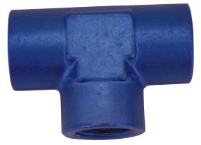
1 1/8" NPT Female T |
The BSPT side of the BSPT to NPT adapter will be screwed into the back of the block using thread sealer. Screw in one of the NPT to AN adapters to the NPT side of the BSPT to NPT adapter using thread sealer. Next assemble the 'T' fitting. Install 2 of the NPT to AN adapters into the 'T' fitting, using the NPT side and thread sealer. Screw in the stock oil pressure sensor into the 'T' fitting using thread sealer. Use the short length of -3AN to connect the oil pressure port to the 'T' fitting, do not use thread sealer. Install the NPT side of the last NPT to AN adapter into the turbo using thread sealer. Run the long length of -3AN hose from the 'T' to the turbo, do not use thread sealer. The 'T' fitting can be secured to something (brake lines, wiring harness, etc..) with zip ties.
The oil return hose runs from the turbo to the oil pan. It is important to realize that the oil flow from the turbo to the oil pan is gravity driven. For this reason the most direct and vertical route should be selected. Larger diameter hose, at least 1/2" (-8AN) should be used. The parts list includes:
|
T3/T4 Oil Drain Flange, 1/2" NPT threads and gasket
|
1/2" NPT to -8AN Adapter
|
-8AN Steel Braided Hose with -8AN hose end fittings
|
-8AN Bulkhead Fitting and Nut Use a straight or 45* fitting depending on your application.
|
The hole in the oil pan for the oil to drain into needs to be above the level of oil in the oil pan. Make the lowest point of the oil pan fitting approximately 1.1" (28mm) down from the topmost part of the oil pan flange. The easiest way to get the oil into the pan is with a bulkhead fitting. DETERMINE THE OIL PAN FITTING LOCATION WITH THE DOWNPIPE INSTALLED. Drill the hole the size of the bulkhead fitting in the pan at the desired location. Insert the long side of the bulkhead fitting into the hole from the outside (long side of the fitting will end up inside the pan). Use the bulkhead nut on the long side of the fitting, use some Hondabond to ensure a seal. The oil pan will be sandwiched in between the fitting and the nut.
A fitting can also be welded onto the oil pan.
Fittings and hose can be found at Baker Precision or Behrents Performance Warehouse The 1/8" BSPT to 1/8" NPT Adapter can be found at Z10 Motorsports Contact Forced Performance for the oil drain flange and gasket.
If you want to adjust the PSI you are running at without changing the internal wastegate spring, want to quickly change the level of boost, or have an internal wastegate and want to raise the boost level then you will need a boost controller. A boost controller works by preventing the wastegate from sensing any boost, and thus opening, until the boost controller senses that the boost level it is set at has been reached. In order for a boost controller to work you cannot set it lower than the PSI level of the wastegate spring. For example, if you have a wastegate with a 10 PSI spring the boost controller will not work at any level under 10 PSI.
There are 2 types of boost controllers, manual and electronic. Below are the advantages and disadvantages to each:
Manual Boost Controllers
Manual boost controllers work on internal mechanisms to manipulate boost pressure before it reaches the wastegate. Manual boost controllers are cheap (compared to electronic boost controllers), fairly reliable, but are not very user friendly. Because the boost setting is made directly on the controller, it cannot be remote mounted for easy access by the user, it must be installed close to the wastegate with minimum hose length. This can be some what of a challenge since the boost controller should also be installed away from high heat. Manual boost controllers are some what difficult to set as well. Since they do not have any quantitative markings on them setting them is a trial and error process. First set the controller at a low setting and run the car, note how much boost is being generated. Increase the setting on the boost controller and run the car again, note the boost level. Continue the process until you reach the target boost level.
There are 2 types of manual boost controllers. The most common is a bleed type controller like the HKS Variable Boost Controller (VBC), Turbo XS Standard Boost Controller, and the Greddy TVVC. These boost controllers work by bleeding off boost pressure to the atmosphere so that the wastegate thinks there is less boost than there really is. For example, let's say that the boost controller is set for 15 PSI and the wastegate has a 10 PSI spring. This means that at 15 PSI the boost controller is letting 10 PSI of boost pressure through the boost controller to the wastegate, the rest is vented to the atmosphere. This type of controller can contribute to wastegate creep just the same as relying on the internal wastegate spring for boost control does. As the boost level, after the controller, approaches the spring's PSI rating the wastegate beings to open which can increase the amount of time it takes to reach full boost. The other type of manual boost controller uses a spring and ball bearing to completely block boost pressure from reaching the wastegate. The Turbo XS High Performance Boost Controller is an example of this type. This design reduces the likelihood of wastegate creep because the wastegate does not see any boost pressure until the set limit is reached.
Electronic Boost Controllers
Electronic boost controllers use three components to regulate boost. All electronic boost controllers use an air pressure sensor, solenoid valve, and a control unit. These controllers are quite expensive (most are over $300), very reliable, and user friendly. The air pressure sensor sends a signal (usually 0-5 volts) that varies as pressure increases to the control unit. The control unit reads the signal and opens the solenoid valve when the set boost level is reach. Since the solenoid valve prevents the wastegate from seeing any pressure there is no chance of wastegate creep. Because the unit is electronic the control box can be installed in the cabin. The pressure sensor and solenoid valve should be installed close to the turbocharger and wastegate, respectively, with short hose lengths and away from high heat sources. Electronic boost controllers also have many useful features such as stored multiple boost settings much like your stereo head unit, scramble boost (high boost at the touch of a button, gear dependent boost levels that vary the amount of boost depending on what gear you're in, and RPM dependent boost settings that adjust boost levels depending on what the engine's RPM is. The HKS EVC, Greddy Profec, Apex-I AVC-R, and Blitz SBC are all examples of electronic boost controllers.
Because we are adding air to the air side of the air fuel ratio with the turbo we must also add a proportional amount of fuel. If there is not enough fuel to compliment the extra air being forced into the cylinders a lean condition will be created which will cause detonation. Detonation is the enemy on a turbocharged car. Detonation is an uncontrolled, very forceful, explosion in the cylinder that can be audible as knocking. If you want to know what detonation sounds like, take a couple of small ball bearings and put them in an empty aluminum soda can. Now shake the can vigorously and remember that sound. If you should ever hear that sound while driving your car you should avoid the condition (usually WOT, wide open throttle) that creates the sound until you can ascertain its cause. Also be aware that a lean condition makes more heat. This can burn pistons, piston rings, valves, and destroy spark plugs. The funny thing is that, generally speaking, leaner fuel mixtures create more power. So we know what can happen if there is a lean condition, what happens if we have a rich mixture (more fuel than than needed). Rich mixtures sap power, foul spark plugs and oxygen sensors, and use more gas than need be. A rich mixture also runs a lot cooler. Of course, nobody has ever blown up a piston by running rich. So as you can see there is a trade off between running lean mixtures and getting maximum horsepower at the risk of doing damage to engine internals, and running rich and losing some horsepower but gaining quite a bit of reliability and safety. The key to all of this is fuel and engine management and tuning.
I know what you're thinking. Aren't fuel management and engine management the same thing? Not exactly. Fuel management is just one aspect of engine management. Fuel management, as the name implies, simply manages fuel going into the motor. Engine management regulates fuel, ignition timing, boost levels, RPM and many other factors. One thing that is common among all options is dealing with the stock MAP sensor. Since Honda engines are not intended to run at positive manifold pressures, the ECU will trigger a Check Engine Light if it senses positive pressure from the MAP sensor. There are 2 ways of avoiding the Check Engine Light, either keep the MAP sensor from sensing boost by using one way air valves called check valves (The Missing Link made by Synapse, is recommended, picture below) or by replacing the ECU, and/or MAP sensor, with an aftermarket unit that can process positive pressure.
Many options for running boost safely on a Honda motor exist, and they don't all include engine management. The different options all offer different levels of cost, reliability, durability, and precision.
Note: The stock Honda fuel line and fuel rail are good to over 400 horsepower.

Extra Injectors
Components RequiredThis option is the least reliable and least precise. The extra injectors add fuel by spraying it directly into the intake charge pipe before the throttle body. The extra injectors are controlled by their own injector controller. With this option, fuel pooling up inside the intake manifold can happen and equal amounts of fuel will not get into each cylinder. This will create different air fuel ratios in each cylinder. Check valves will be required to keep the MAP sensor from sensing boost, a Missing Link check valve is recommended but plastic aquarium check valves could be used. This option should not be used for anything over 200 horsepower or about 8 PSI, if at all.
Boost Dependent Fuel Pressure Regulator with Stock Injectors
Components Required
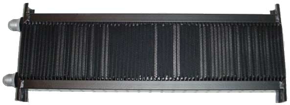
With this option the stock Honda injectors, which are 245cc, are used with a boost dependent fuel pressure regulator. A boost dependent fuel pressure regulator increases the fuel pressure a set amount for every PSI of increased boost pressure. Most boost dependent fuel pressure regulators are modeled on Vortech's Fuel Management Unit (FMU) and look like the below picture. In most applications a 12:1 ratio FMU will suffice. This means that at any given boost PSI the fuel pressure will be 12 times that amount plus the stock fuel pressure which is about 40 PSI. For example, at 6 PSI the fuel pressure added by the FMU will be 72 PSI, added to the stock 40 PSI, will be 112 PSI of total fuel pressure. As you can see this is a lot of fuel pressure for the stock fuel system to take. Because the system is stressed so much more than it was designed for it is more likely that there will be a failure, especially an injector failure. If an injector failure occurs, sever engine failure will occur. Check valves will be required to keep the MAP sensor for sensing boost, a Missing Link check valve is recommended but plastic aquarium check valves could be used. The maximum safe limit for this setup is 6 PSI, going over this amount of boost will increase the chances of an injector failure.
Boost Dependent Fuel Pressure Regulator with Larger Injectors
Components Required
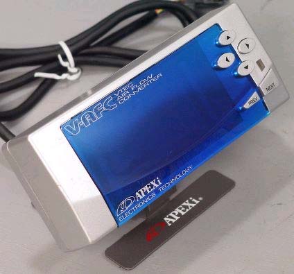
This is similar to the above option but instead it uses larger injectors and an Apex-I AFC to control them. With this option you can use a 12:1 or 10:1 ratio on the Vortech FMU depending on injector size. When replacing injectors it is important to match the correct type of injector with the correct OBD version of ECU. If you have a 90-91 Integra you have an OBD0 PR4 computer that uses peak and hold, low resistance, injectors. If you have a 92-93 Integra, or any VTEC engine, you have an OBD 1 PR4 computer that uses saturated, high resistance, injectors. When buying new injectors (available from RC Engineering) get the correct type for your application. If you must use peak and hold injectors on a OBD1 or later car, then follow the directions in the next section for adding resistors to the wiring harness. A high pressure fuel pump such as the Walbro 255lph pump or MSD High Pressure Fuel Pump PN 2225 is necessary to provide fuel at the high pressure that will be required. The Walbro pump can be installed in-tank or inline while the MSD pump can only be installed inline. If running the pump inline, disable the stock fuel pump. Although it is not necessary to remove the stock fuel pump, know that pumping fuel through the disabled stock fuel pump will slightly limit flow rates, but not pressure. Steel braided lines are a good idea given the amount of fuel pressure that will be required. The stock hard fuel lines and the stock fuel rail are good to over 400 horsepower, they do not need to be replaced. The Apex-I AFC (shown below) is used to de-tune the injectors so they will allow the car to run normally at idle and at low, partial throttle RPM. Check valves will be required to keep the MAP sensor for sensing boost, a Missing Link check valve is recommended but plastic aquarium check valves could be used. A common setup with this option is to use 320cc injectors which is good to about 12 PSI. Going much higher is very risky with an FMU setup.
AFC Hack
Components Required
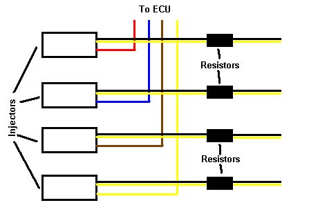
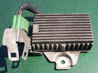
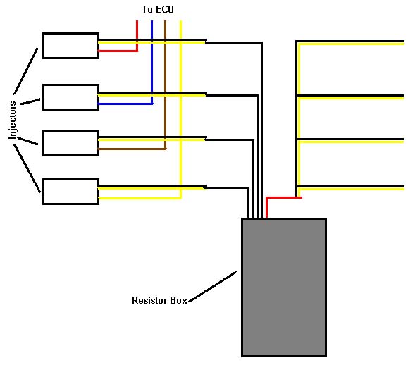
First let me say that 'AFC Hack' is a poor name for this setup. The AFC is not being hacked in any way. Installation of the AFC is per manufacturer's instructions. The only thing that can be considered 'hacked' is the MAP sensor signal wire, but even that is stretching it. This setup is the cheapest way to mimic how a factory turbocharged engine runs. Factory turbocharged engines do not use rising rate fuel pressure regulators to add fuel, they use large injectors instead. Unfortunately adding larger injectors with nothing to control them but the stock Honda computer does not work. The stock computer is tuned for 245cc injectors, adding an injector twice that size will get you twice as much fuel per injector pulse. The most popular source for the 450cc injectors is from the 90-99 manual transmission equipped, turbocharged, DSMs. You can find these injectors for under $100 on ebay.com. These injectors are low resistance, Peak and Hold, injectors which will not run properly on an OBD1 or later engine without some modifications to the engine wiring harness, for OBD 0 (90-91 Integras) no modifications are required. In order to run these low resistance injectors on OBD1 or later engines, resistors must be added to the injector wiring harness. There are 2 ways to accomplish this, wire the resistors inline with each injector or by using the resistor box from a 90-91 Integra. If you chose to wire in resistors inline on each injector wire then you will need 10watt 10ohm resistors (they look like the picture below) which can be found at Radio Shack. Solder one resistor into each black and yellow wire for each injector (see wiring diagram below). If you chose to use the resistor box (see picture below) then you will need to do a bit more cutting and soldering. The resistor box has 4 black wires and one red wire. After cutting the black and yellow wires solder each of the black wires from the resistor box to each of the black and yellow wire that leads to the injectors, it does not matter which black wire in the resistor box goes to which injector. Be sure the black and yellow wires you find are actually the injector wires by checking for continuity on the injector connector. Now we need to connect the red wire from the resistor box to all 4 of the other black and yellow wires. It is best to use a butt connector to do this, if you try to solder all these wires together you will end up with a large ball of solder. See the wiring diagram below for using the resistor box.
|
|
  |
If you are not confident working with electronics, or with soldering, then find someone to do the work for you. Solid soldering is very important, having a soldered connection come apart while at full boost would be very bad in this situation.
To supply these larger injectors with fuel you will need a high flow fuel pump such as the Walbro 255lph pump. This pump can be installed inline or intank. If running the pump inline, disable the stock fuel pump. Although it is not necessary to remove the stock fuel pump, know that pumping fuel through the disabled stock fuel pump will slightly limit flow rates. The stock fuel lines and the stock fuel rail are good to over 400 horsepower, they do not need to be replaced.
With the AFC Hack method of fuel management, the AFC is installed as per manufacturer instructions. The AFC should be set as follows:
These settings can be adjusted ± 5% to fine tune for your application. Also, if you have an adjustable fuel pressure regulator (not a rising rate regulator) experiment with raising and lowering the fuel pressures.
This setup is good to about 12 PSI max since that is the limit of the Honda MAP sensor. This setup is very reliable and more precise than the above methods.
Check out http://www.thedropshop.tv/vafc.htm and http://www.honda-tech.com/zerothread?id=137901 for more information.
Stand Alone ECU: Hondata or Zdyne
Components Required
Using a standalone ECU will allow your turbocharged Honda to run as if it had come from the factory with a turbo. This option offers complete engine management in an easy to install package. In both cases the ECU plugs into the stock Honda wiring harness. The real advantage to this option is the high level of adjustability and precision you have over both fuel mixtures and ignition timing. Both ECUs are quality products that offer the ultimate in engine management for turbo applications. As with the other fuel management options larger injectors and a high flow fuel pump like the Walbro 255lph are recommended. This pump can be installed inline or intank. If running the pump inline, disable the stock fuel pump. Although it is not necessary to remove the stock fuel pump, know that pumping fuel through the disabled stock fuel pump will slightly limit flow rates. A common size injector for this setup is 720cc. A 3 Bar map sensor will be required if running over 12 PSI of boost. The 3 Bar sensor will allow you to run up to 30 PSI.
If you have a 92-93 Integra or any non OBD0 engine (or you've converted your OBD 0 engine to OBD I or OBD II) then Hondata is the system for you. Hondata offers 2 systems, the S100 and S200. The S100 is the base system. It lacks the data logging capabilities, launch control, G sensor, and adjustable VTEC controls and rev limiter. The S100 uses the same programming software as the S200. The S200 offers extra options such as the ones that are missing from the S100. If you have a laptop computer and the equipment to burn ROM chips you can tune the ECU yourself.
The AEM system offers many of the same capabilities as the Hondata system for non OBD0 cars. The EMS system plugs into the stock wiring harness and is tuned with a PC computer. The EMS does have datalogging capabilities.
http://www.aempower.com/product_ems.asp
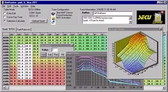
Zdyne is the option for OBD 0 applications like the 90-91 Integra. Like Hondata, Zdyne offers 2 systems that support turbo applications, the Silver SECU and Gold SECU. The Silver SECU is not user adjustable and comes with a preprogrammed engine tune that will work for most boosted applications. The user can select options such as hot and cold rev limits, and VTEC and NOS activation RPM levels which are programmed at the factory. The Gold SECU offers full user adjustability of fuel and timing curves through the use of a Windows based application and a serial cable to connect to the ECU, no ROM burning. None of the systems offer data logging.
Both of these options are well supported by most shops that run a dyno and offer tuning services. Unless you have the equipment (wide band oxygen sensor and/or exhaust gas temperature gauge) and experience it is recommended that the ECU be setup and tuned on a dyno.
Other Options
SMC - Super Map Controller - The SMC is alternative the the Apex-I S/V AFC. It is a bit less refined and not as user friendly but it is considerably cheaper than the AFC. Note that manufacturing standards may not be on par with the Apex-I unit. Some dyno tuners have been known to not work with the SMC due to its questionable quality.
Check out http://userwww.sfsu.edu/~ecg/SMC/smcmain.htm
Uberdata - Cheaper alternative to Hondata and Zdyne. If anyone has specific, reliable, information on its capabilities and specs send them to turboguide@beesandgoats.com and I'll add them here.
Motec, Electromotive, et al. - These are serious engine management options that are used primarily on race cars. Before Hondata and Zdyne these were the systems being used (actually way back in the day turbo Hondas were converted to carburetors). These systems are anything but user friendly. To use them all the engine sensors must be swapped for the system's sensors requiring a complete rewire of the engine wire harness. These systems are difficult to get running reliably on street driven cars. They can also cost quite a bit of money.
Ignition Management
If you are using fuel management only something will have to be done to separately control the ignition timing. One option is to simply retard the timing physically (moving the distributor) to around 12* BTDC. This will retard the entire timing curve and make off boost, low RPM, power a bit sluggish. The other option is to use a MSD Universal Boost Timing Master (BTM) PN 5462 which will adjust ignition timing per pound of boost. This system has a small dial that is installed in the cabin. Turn the dial to adjust the amount of timing retard it applies per pound of boost. Try setting the system between 0.5* and 1* of retard per pound of boost. If detonation occurs add more retard.
Another option is to use a J&S Safeguard. The J&S Safeguard uses a knock sensor to retard timing on each cylinder individually. This system offer particularly good safety because it can detect detonation at levels that cannot be heard. A very good investment.
Tuning
If you have fuel or engine management that requires tuning it is best that an experienced tuner do all the adjustments. Tuning is best done on a dynamometer so that the result of tuning can be evaluated quantitatively. It's also best that a tuner have a wide band air fuel ratio gauge (FJO www.fjoracing.com) and/or an exhaust gas temperature gauge (EGT). The gauges will also tell you the results of any tuning changes. Some people keep wide band air fuel ratio gauges in their cars, but at about $800 they are an expensive, and easy to steal, investment. An ideal temperature for the EGT is 1200* - 1400* F which should result in about a 14.7- 15.0 air fuel ratio on the wide band. The best way to tune the engine is to start out with some base setting that are on the rich side. As mentioned above, rich mixtures are safe mixtures. Make small, incremental, changes in the A/F and ignition timing. If at any time you get detonation you know you've gone to lean or haven't retarded the timing enough.
For more information on tuning check out A/F and EGT gauges http://www.sdsefi.com/techegt.htm
Now that we've covered the basic components of a turbocharger system we'll cover some of the other things that can be done to complement the turbo and make things more reliable. This includes whether to buy a kit from a company such as Drag or assemble your own kit, addressing the cooling, PCV, ignition, and drivetrain systems to make them work better with the turbo. The more time spent addressing these concerns the more reliable your setup will be and the happier you will be with the out come of your turbocharged Integra.
Many companies offer kits that have most everything you need to turbocharge your Honda. Some kits are better than others and many different retailers offer the kits at different prices. The advantage to buying a kit is that all the parts are designed to work together, the kit is designed for your specific car, and you get installation instructions. Perhaps the biggest advantage is the pipe routing is designed for your car (as long as you use their turbo manifold and turbo). The disadvantage is that you may not get the best components, the best craftsmanship, or the best support. These kit manufacturers goal is to make a profit and they will cut corners by supplying mediocre parts and sacrifice quality on welds and materials in the intake and intercooler pipes. The most common example of this is the wastegate that is offered with the kits, a Turbonetics Deltagate. Some kit manufacturers or retailers selling the kits will offer to exchange parts in the kit for a higher price. Also a lot of these kits scrimp on the engine/fuel management which can limit the potential of the kit. If you decide to use some kind of engine/fuel management other than what is offered in the kit you still have to pay for the engine/fuel management components that come with the kit. You could probably unload these components on ebay. Another consideration is that no kit is truly bolt-on as most people think. Installing a turbo kit is not as easy as installing a cold air intake, some cutting and engine bay component relocation may be necessary. Below are some of the advantages and disadvantages of the kits offered by several of the manufacturers:
The Drag kit offers a cast manifold (with the wastegate port in a poor position) with a Deltagate wastegate (7 PSI spring) and a T3/T04B turbo. The wastegate is dumped to the atmosphere with this kit. The downpipe is routed to the driver side. Air conditioning and power steering can be retained with this kit. Block shaving is required to get the turbo to fit. For fuel management the kit offers a Vortech FMU, high pressure fuel pump, and check valves for bypassing the MAP sensor. The intercooler does not have brackets for mounting, these will have to be fabricated and welded on during installation. Intercooler pipe quality with this kit is questionable. The kit does offer an air filter assembly. Without adding larger injectors or a boost controller this kit is limited to 7 PSI.
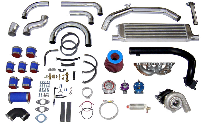
Rev Hard's kit offers a cast turbo manifold (with a slightly better wastegate port position) with a TurboSmart wastegate (7 PSI spring) and a T3/T04E turbo. The TurboSmart wastegate is very new player in the industry and not much is known about this wastegate's performance or reliability. The wastegate is vented to the atmosphere in this kit. Rev Hard claims that the air conditioning cannot be retained however with some customization this may not be true. Power steering can be retained. Fuel management components supplied with this kit include a Vortech FMU, high pressure fuel pump, and Missing Link check valve for bypassing the MAP sensor. A 28x6.5x3 Rev Hard intercooler is included in the kit. This kit does not offer a filter assembly. Without adding larger injectors or a boost controller this kit is limited to 7 PSI.
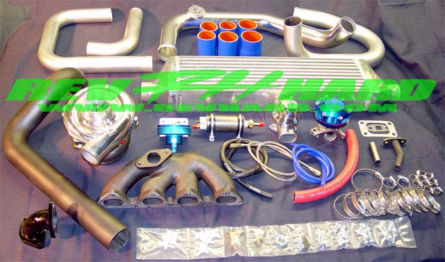
FMax Fabrication (Turbonetics)
In 2003 FMax Fabrication was bought out by Turbonetics. This kit offers a cast manifold with the wastegate post in decent position. The turbo is a T3/T04B and a Turbonetics Deltagate is included. Air conditioning and power steering are retained. Fuel management with this kit is provided by 2, 450cc injectors which spray directly into the intake charge pipe. The kit does include a MSD BTM to manage ignition timing, which is a plus (but doesn't make up for the extra injector fuel management). The kit does offer an air filter assembly. With this type of fuel management boost is limited to 7 PSI.
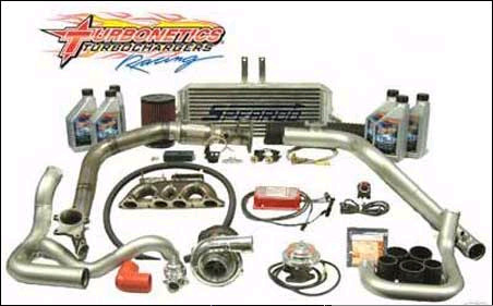
Custom Kit
The alternative to a kit from one of the above manufacturers is to assemble your own kit. The advantage here is that you can get the best components for your application and you will learn a lot more during the process of researching which components you should get.. You will not get into the situation where you have to spend money on parts that you do not want to use like you can get into with a manufactured kit. Not only can you specify your own components but you can install them how you want to install them. Putting together your own kit does not have to be expensive either. Using resources such as Group Buy Center, The Parts Trader, ebay, and the classified section on many message forums can yield some great deals on quality parts. Perhaps the big disadvantage to putting together your own kit is that all the pipes will have to be fabricated, however, some of the above manufacturers will sell pipe kits. Some of local speed shops will give you a deal on all the parts you specify if you also have them do the labor for installing the kit. This can be a good deal but it is important that you stay on top of the people doing the work so that they do it the way you want it done. If you install the kit yourself not only will you be saving yourself some money but you will also learn a lot about the turbocharger system.
Besides engine management and tuning, engine cooling is one of the most important issues with regards to engine reliability when adding a turbocharger. Increasing the amount of horsepower also proportionally increase the heat generated by the motor which is transferred to the coolant and oil. Also consider that there is a lot more exhaust system surface area to radiate heat into the engine bay, this heat will often soak into the radiator since the two components are so close together. Many turbo Honda owners do not run any aftermarket gauges to keep tabs on water and oil temperatures, instead relying on the horribly inaccurate OEM instrument cluster water temperature gauge. Because of the lack of a water and oil temperature gauge many turbo Honda owners do not have any idea that their engine runs hot which decreases engine life. Many people may argue that their engine has never overheated, using that fact to conclude that there are no problems with their cooling system. Just because an engine does not overheat does not mean damage is not being caused.
Ideal water temperatures are around 180* but not over 210*. If your turbo positioning and pipe routing allow it, a full size radiator should be used. An aftermarket aluminum radiator like those from Fluidyne are an excellent addition and will solve any water cooling problems. Sometimes in order to use the full size radiator (stock or aftermarket) the cooling fans will need to be moved to the front of the radiator to push air through the radiator instead of pull air through like the stock setup. To do this, it is recommended that aftermarket fans such as those that are available from Spal and Permacool be used. The largest fans that can be fit on the radiator core should be used. The target total flow rate for the fans should be around 2000 CFM. These fans are not direct bolt in fans, to mount them you'll have to use a universal mounting kit which includes nylon push through ties and end caps. The ties resemble thick zip ties that hold the fans to the radiator core (see picture below) by being pushed through the fins in the core. The fans can be spliced into the stock wiring harness.
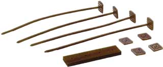
If your turbo position and pipe routing will not allow the use of a full size radiator, a Civic half radiator can be used. If one of these radiators must be used it is highly recommended that an aftermarket one (Fluidyne) be used. Due to the decreased surface area, and increased thickness, these radiators provide less cooling than the full size counterparts. Also consider that the radiator is being placed behind an intercooler which increases the air's temperature going through the radiator. For the same reason that thicker intercoolers are not as efficient as longer or taller intercoolers, a thicker Civic radiator is less efficient than a full size radiator. By the time the air has gone through half of the core it's capacity to absorb more heat is greatly reduced. To mount one of these radiators in the 90-93 Integra, drill out the spot welds that hold the stock radiator mounts in place and either reweld or bolt them into the position you need them in. Also note that you may need to remount the mounts lower so that the top of the radiator clears the hood.
The best coolant you can use is distilled water with Red Line Water Wetter. Of course if you're in an area where temperatures get below freezing this is not an option, at least in the winter.
High oil temperatures, particularly, cause engine failures. Water and oil temperatures should be about equal with ideal temperatures around 180* but not over 210*. As oil heats up over a certain point (different with each different brand and weight of oil) it breaks down molecularly and provides less and less lubrication. This is the primary killer of engines that many people don't know about because they don't use oil temp gauges. Many turbo Honda owners are oblivious to the high oil temperatures they are running, temperatures of over 230* are common after running the turbo hard for a long period of time. To combat these high oil temps an oil cooler should be used. Permacool and Setrab offer excellent oil coolers. Unfortunately it's not as simple as installing an oil cooler and calling it a day, oil can be to cold too. Oil needs to be a minimum of 150* to lubricate effectively. To get the oil up to operating temperatures it must be diverted from the oil cooler with an thermostatic oil bypass valve (available from Permacool). The parts list for adding an oil cooler include:
|
Oil Cooler An oil cooler size of 10.25"x4.5"x1.75" works well.
|
Sandwich (top) or Spin on Adapter (bottom) M20x1.5 Threads (Permacool) This goes where the oil filter is. If planning on leaving the oil filter in the stock location use the sandwich adapter. If you want to relocated the oil filter use the spin on adapter (more information below).
|
Thermostatic Oil Bypass Valve (Permacool)
|
1/2" NPT to -8 AN Adapters
|
Steel Braided Hose and -8 AN Hose Ends
|
If adding an oil cooler it is a perfect opportunity to relocate the oil filter as well. With the filter relocated oil changes become much easier and a lot less messy. Adding a remote oil filter also allows for the use of a larger oil filer. The parts list for adding a remote oil filter includes:
|
Remote Oil Filter Mount (Permacool) Mounts are sold with the ports facing left, right, or up. Decide where the mount will be installed then select the appropriate mount with the ports facing the appropriate direction.
|
Spin on Adapter (bottom) M20x1.5 Threads (Permacool) This replaces the oil filter.
|
1/2" NPT to -8 AN Adapters
|
Steel Braided Hose and -8 AN Hose Ends
|
Oil capacity will be increased if adding any of these components, don't forget to add more oil.
To reduce underhood temperatures, try removing the weather stripping that is on the cowling just below the windshield. This will allow more air to flow over the top of the engine and evacuate more hot air from the engine bay. If you still want more cooling you can put washers in between the hood hinge bracket and the hood, this will raise the back of the hood making a larger gap in between the cowling and hood, allowing even more air to exit the engine bay.
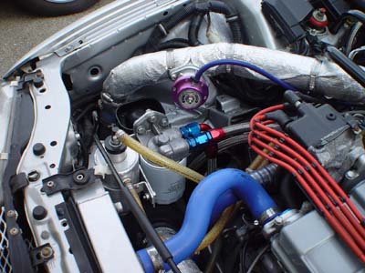
The positive crankcase ventilation system exists to relieve positive air pressure from the crankcase. Pressure in the crankcase is created by piston ring blow by and by the up and down motion of the pistons (just as the piston seals the top of the combustion chamber it seals the bottom of the cylinder, pulling air in on the compression and exhaust stroke, pushing air on the intake and power stroke). In order to relieve this pressure, a vacuum pressure sucks the pressure out of the crankcase through the PCV system. If the pressure is not vented piston ring and piston ring land damage can occur from the rings being jostled around as the piston is drawn down towards the crankcase, fighting against the pressure. In a turbo application this system must be modified or it will not work. Before figuring out how to modify the system it is a good idea to see how the stock system works. Below is a diagram of the stock PCV system:
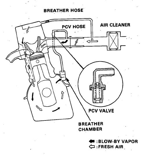 |
As you can see the system begins in the intake pipe where air enters a hose that is attached to a barbed fitting on the valve cover. It is important to realize that the fitting on the valve cover is the PCV system inlet, air goes into the valve cover here. The air flows down through the head and into the crankcase. Once in the crankcase the air will pick up oil vapor from the oil being slung around at high velocity by the rotating assembly. The air then flows through the 'breather chamber' which is the black box you see on the back of the block under the intake manifold. The breather chamber has baffling in it that separates out some of the oil vapor and allows it to drain back into the crankcase. A hose connects the breather chamber to the PCV valve. The PCV valve is a one way valve that is open when a vacuum pressure is applied to the top of the valve. The PCV valve is connected to the intake manifold with a hose. The intake manifold exerts a vacuum pressure on the entire system. The PCV system is a closed vacuum circuit with pressure being exerted on one end and vacuum on the other. This allows any positive pressure in the crankcase to be vented. The problem when a turbocharger is added is that the intake pipe and intake manifold become pressurized. If the fitting on the valve cover is still connected to the pressurized intake pipe it will pressurize the crankcase too. At the same time, the PCV valve will close when pressure is exerted on the top half of the valve, sealing the crankcase. If no modifications are made to the system a pressurized and sealed crankcase will occur when the boost kicks in, this is the worst possible time to have a sealed and pressurized crankcase. There are quite a few different opinions on how to plumb the PCV system for a turbo application. As long as the crankcase is not being pressurized by the intake charge pressure and the crankcase has some way to vent pressure you'll be in good shape. Probably the worst thing you can do is to add a valve cover breather filter to the fitting on the valve cover and retain the plumbing for the stock PCV valve. This would force the crankcase to vent through the valve cover breather filter. Many of the popular turbo PCV options include the use of a catch can. The catch can has internal baffling that separates out more oil vapor from the system. This is important because oil vapor effectively lowers the octane rating of the gas you are using, making detonation more likely. The catch can of choice is the Moroso Dry Sump Breather Tank Moroso part# 85470. The catch can needs to have 2 fittings on it. One is provided by way of a port on the side of the can. The other must be added by inserting a grommet into the top of the can (Help! PCV Grommet # 42048 for a Ford Econoline Van), and then a barbed fitting into the grommet. See picture below. Below are a couple common turbo PCV plumbing options. |
|
This setup mimics the stock setup PCV system. The inlet to the PCV system is in the pre-turbo intake pipe. A 90* fitting (a bulkhead fitting would work, or a bent piece of metal tube) with the opening facing towards the filter will allow incoming air to flow into the system. The air then flows into the valve cover, into the crankcase, and then out of the PCV valve port which now has a simple plastic 90* barbed fitting (no PCV valve). From the PCV port the air flows into the side of the catch can and out of the top of the can. Air then flows back to the pre-turbo intake pipe. For the PCV system outlet another 90* fitting is placed with its opening facing the turbo. This routing sets up a closed circuit system with pressure being exerted on one end and vacuum on the other. |
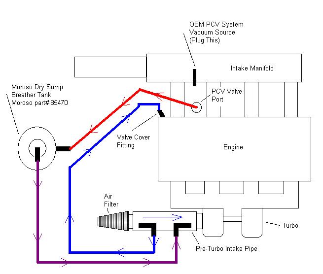 |
 |
This routing is a little simpler than the one above. The valve cover fitting has a breather filter on it. Air flows through the crankcase and out of the PCV port which now has a plastic 90* barbed fitting in it (no PCV valve). From the PCV port, the air flows into the side of the catch can and out of the top of the can. Air then flows back to the pre-turbo intake pipe. A 90* fitting is not required here because air flowing across the opening of the fitting in the intake pipe will draw air out in the direction of air flow (the same reason water comes out the top of a straw when it is submerged in a glass of water and you blow across the top of it). This routing is not a closed circuit system with the only drive for the system being provided by vacuum.
Thanks to xenocron from G2IC for this PCV plumbing option. |
The stock Honda ignition system is quite capable of supporting a turbocharged engine. It is recommended that a cold spark plug, such as the NGK BCPR7E-11, be used. These plugs can be hard to find, so if you do find them it would be smart to buy a few boxes of them. The gap on the plug will need to be reduced to about .0.03". Stock spark plug cables or NGK cables are better than any other out there. They fit onto the distributor posts and spark plugs very well. As mentioned above, you can use a MSD Universal Boost Timing Master (BTM) PN 5462 to adjust ignition timing per pound of boost. This system has a small dial that is installed in the cabin. Turn the dial to adjust the amount of timing retard it applies per pound of boost. Try setting the system between 0.5* and 1* of retard per pound of boost. If detonation occurs add more retard. Otherwise you will have to retard the timing physically (moving the distributor) to around 12* BTDC. This will retard the entire timing curve and make off boost, low RPM power a bit sluggish. Other ignition boxes, such as the MSD 6 Series and Crane Cams HI6, are good for their ignition cut rev limiter. The stock Honda rev limiter works by cutting the fuel, which is a bad thing when at full boost. Cutting the ignition is much safer, but remember that the ignition cut rev limit must be below the stock Honda's rev limit so that the ignition cut rev limit is reached first.
First let's get one thing straight, torque is the factor that should be examined when discussing the drivetrain, not horsepower. Torque is a measure of the actual force being applied to the drivetrain. An engine making 250 horsepower and 230 foot pounds of torque will break parts before an engine making 250 horsepower and 210 foot pounds of torque will. Broken parts occur from resistance to the torque trying to turn the wheels. You are much more likely to break parts if you are running slicks, for example, because it takes so much more force to turn the tire than a street tire. That being said, the stock Honda drive train is surprisingly resilient when a turbocharger is added, but it does have a couple weaknesses. The first thing in the drivetrain that you should consider upgrading is the clutch assembly. Clutches like Clutchmasters and ACT are excellent clutches. Select the pressure plate and clutch disc that match your torque numbers. Note that full face clutch discs will tend to be more streetabale than the 'puck' clutch discs. Another weakness of the stock drivetrain is the differential. The stock, non-limited slip differential, is what causes torque steer. Torque steer occurs when a disproportionate amount of power is diverted to one wheel causing the car to steer without you turning the steering wheel. The stock differential is also not very strong, especially when exposed to clutch drops and power shifting. Below are some pictures of what happens to an abused stock differential, this happened at only 210 ft lbs of torque. Unfortunately the only option for curing this problem is to use an expensive limited slip differential like that available from Quaife.
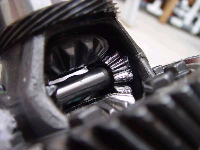
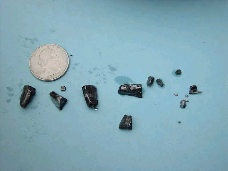
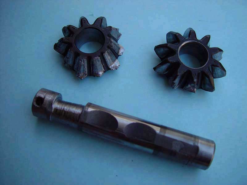
The last weakness that you need to know about are the stock half shafts. With enough power and enough abuse these can snap quite easily. There are aftermarket replacements available from companies such as ENJO and The Drive Shaft Shop .
There is a lot of controversy over lightened fly wheels in a turbo application. Some believe that since a turbocharged engine moves through the lower gears so fast, adding a lightened fly wheel would make it move through those gears even faster, making it even more difficult to maintain traction than it already is in a front wheel drive turbo car. Others want to get to higher revs as quickly as possible to make use of turbochargers that provide power at high RPMs. For street drivability, this author recommends the stock fly wheel. If you do chose to go with a lightened fly wheel do not get the lightest one possible. Most lightened fly wheels are designed with naturally aspirated, high revving (low power compared to what a turbo Honda puts out) applications in mind. With all the added power being put through the fly wheel from the turbo a lightened fly wheel is more likely to fail the lighter it is.
As mentioned above, torque breaks parts. But how that torque is used lends even more to parts breakage. Constant burn outs, clutch drops, and power shifts will take their toll on drivetrain parts. I know it's hard to resist doing these things with a turbocharged engine, but the kinder you are to your tranny, the less money and time it will demand of you. It's also wise to learn to rev-match on your downshifts. Rev-matching is making the engine speed equal to the transmission speed that you will be down shifting to. It's easy to do: clutch in, select lower gear, briefly hit the gas (called blipping) to bring the revs up, and then let out the clutch. If you do all of these steps while pushing on the brake pedal (leave the left side of your right foot on the brake, the right side of your right foot blips the throttle) you'll be doing heel and toe downshifting. If you use these techniques you will add a lot of life to your clutch and gear synchros
Turbocharged Hondas with automatic trannys have been done but the torque converter is a severe limitation. The torque converter cannot take over 200 horsepower. At the time of the writing of this guide no aftermarket torque converters are available. A swap to a manual transmission is highly recommended.
One last tip that is partially related to the drivetrain...replace those POS stock Honda shift linkage bushings. Prothane and Energy Suspension both offer polyurethane bushings that will take out a lot of the slop in your shifter. Using the solid aluminum bushings that are available from B&M will remove all the slop from your shifter, but it will make it rattle too. The best compromise is to use the B&M bushing on the transmission and one of the polyurethane bushings on the shifter end of the linkage.
What are Porsches best known for? No, it's not turbo power. Long before Porsches had massive power, they had awesome brakes, they still do. With all the power you are adding you would be very wise to add some braking power. Brake pads such as EBC or Axxis are a wise investment as are steel braided brake lines. A turbo Honda can build a lot of speed quickly, it is just as important to be able to reduce that speed quickly.
The Honda engine bay is a crowded place. A lot of room can be gained by removing the power steering and air conditioning components. By removing the components, the turbocharger related components can be placed in the most ideal places. Wastegate positioning, downpipe routing, and intercooler piping are all much easier to place.
The power steering is perhaps the easiest system to do without. Power steering is only active at low speeds. Keeping tires properly inflated helps a lot with being able to turn at low speeds without the power steering. To help decide if you want to keep it or not, try removing the power steering belt for a while. Removal of the power steering also provides more feedback through the steering wheel. If you do decide to keep the power steering something must be done with the power steering fluid cooler that runs in front of the radiator. This fluid cooler can be removed, in place of it simply use a high pressure, oil resistant hose to connect the 2 ends.
The air conditioning primarily effects the downpipe and intercooler pipe routing. Because of the proximity to the AC compressor the downpipe must by run with a tight radius or 2.5" pipe must be used. The other option is to run the turbine housing on the passenger side of the car, but running it this way still require tight radius bends. If you keep the AC the intercooler pipe must be run through the area behind the bumper where the windshield washer fluid reservoir was because of the AC condenser's location in front of the radiator. Also the AC fan (mounted on the driver side of the radiator) will probably not clear the turbo requiring the fan's removal. This will reduce the AC cooling ability. The air conditioning lines that run near the top of the radiator should be covered in some heat reflective insulation (available from www.thermotec.com) to protect them, it may also be necessary to move them slightly so they don't contact the turbo or manifold.
Relocating the battery to the trunk opens up a large amount of room in the cramped engine bay. This space can be used to add an air filter (if the compressor is on the passenger side) or any number of other components such as ignition boxes, oil filter, and the PCV catch can. Putting the battery in the cabin with passengers does present some problems. As a battery charges, it creates hydrogen from the battery posts (a sealed battery won't even prevent this), hydrogen build up in the cabin is not a good thing. Also if the battery were to break open, acid vapor could fill the cabin. To prevent these problems, a sealed battery box like that from Moroso (see bellow) should be used. The Moroso box lid has a rubber strip on the inside of it to seal the box. The easiest place to add the box and battery is in the rear most corner of the rear hatch area. This position will allow access to the spare tire well and easy routing of battery cables (Moroso has a battery cable kit, see below) down the side of the car. Installation is easy. Determine the position of the box, drill 2 holes through the box and through the floor of the car (mind the rear tow hooks), then bolt the box to the floor. With the Moroso box, the bolts used to bolt the box into the car also serve as the battery retaining bolts. Drill holes in the side of the box and side trim piece to run the cables through. Wire the cable up to the main engine wiring harness to supply power (check your repair manual's electrical system diagrams). If you plan to run your car on a NHRA sanctioned track you will be required to have a bolted in, sealed, battery box to pass tech if the battery has been relocated. Depending on how serious the techs are at the track, they may also require a rear accessible battery master cut off switch. This means a switch that can be accessed from to the rear and outside of the car that shuts all power off must be installed. This is so when you crash they can turn off all power to the car quickly.
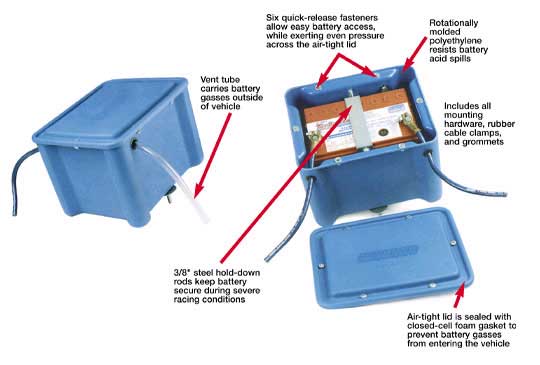
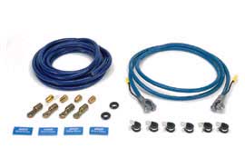
Aside from your butt and your ears, gauges are the only way to keep tabs on what your engine is doing, and your butt and ears aren't very reliable. There are 2 types of gauges, mechanical and electronic. Mechanical gauges are operated directly by what ever they are monitoring. Electrical gauges have a sender unit that sends an electrical signal to the gauge which interprets the the signal and operates the gauge accordingly. Use mechanical gauges for the pressure gauges, pressure can change quickly (electric gauges react slow), electric is fine for temperatures since temps are slow to change. The bare minimum gauges you should have are water temperature, oil pressure, boost, and an air fuel ratio (Autometer) gauge. For the oil pressure gauge, do not use the nylon hose that comes with the gauge, instead use -3AN steel braided hose. The oil pressure signal will have to come from the 'T' fitting where the turbo oil feed hose is, just add another 'T' fitting to the one already being used. The turbo oil feed hose should be attached to the first 'T'. It is OK to use the nylon hose for the boost gauge, see the picture below for an example on how to install. An exhaust gas temperature (EGT), fuel pressure, wide band air fuel ratio gauge and oil temperature gauge are also wise investments. For the oil temperature gauge sender, it installs much like a bulkhead fitting (drill a hole in the pan, insert sender, seal with Hondabond), install it just above the oil drain plug in the oil pan. Before you get all hot and bothered about the Autometer A/F gauge being imprecise, realize that it's use is for monitoring, not tuning. The Autometer A/F gauge will tell you when your fuel mixtures are rich and when they are lean but don't count on being able to assign any quantitative valve to how rich or how lean. For tuning purposes, look to the wide band air fuel ratio gauge (available from FJO) and the exhaust gas temperature gauge. It is also a good idea to install a simple fuel pressure gauge on the end of the fuel rail for dyno tuning purposes, when installed in this position it is easy to watch during a dyno run.
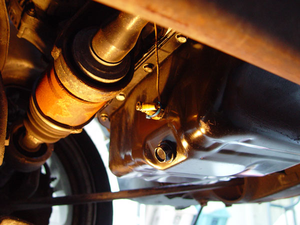
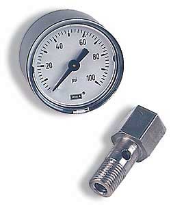
A turbo timer is used to keep the engine running for a set amount of time even though the key has been removed from the ignition. This is done to keep oil, and water if applicable, running through the turbo to allow the turbo to cool down without you having to sit in the car to manually turn it off. The turbo timers come with security features that prevent someone from jumping in your running car after you've gotten out. These security features usually work by turning off the engine if the parking brake is released or if the clutch pedal is depressed. Most timers have circuitry that will allow a car alarm to arm even with the engine running. A turbo timer works by intercepting the ignition switch signal to the computer, keeping the ignition on when the ignition switch is off. If you have an oil temperature gauge it is easy to judge how long the turbo timer should be set for. The harder the turbo has been run or the hotter the oil the longer the timer should be set for, usually 1-2 minutes is sufficient. HKS, Greddy, Apex-I, and Blitz all make quality turbo timers.
Getting a turbo Honda to run clean enough to pass a smog test can be difficult, especially without the adjustability of a stand alone ECU. In California you can forget about passing a smog test, it won't happen, you'll fail the test on the underhood inspection and won't even get to the dyno/sniffer test. In California your options are to remove the turbo components, reinstall all the stock stuff, take the test, then reinstall the turbo. This may not be as bad as you think, since smog tests are required every 2 years, removing the turbo will give you the opportunity to look over everything and fix any problems. The other option is to get a smog certificate illegally, which can cost quite a bit these days (I'm not advising you to do this, I'm just telling you what some people do). If your state's smog test only consists of a sniffer test then you may be able to pass but it may take a couple of tries to get your car tuned so that it will pass.
The catalytic converter is a significant flow restricter in the exhaust system, even presumably 'high flow' cats. You can expect as much as a 30 horsepower gain by removing the cat. Having the cat in the system will also contribute to extremely sluggish low RPM performance. However removing the cat in most areas of the country is illegal and results in a heavy fine, remove it at your own risk. One option to reduce the chance of being caught it to have a fake heat shield that looks like a cat's heat shield welded onto a straight pipe, making it look like a cat (Again, I'm not advising you to do this, I'm just telling you what some people do).
| JE
/ SRP - Pistons
Crower - Pistons, Stainless Steel Valves Golden Eagle - Rods, Sleeves, Block Gaurd, Vacuum Manifold Arias Pistons - Pistons STR - Block Gaurd Revhard
- Manifolds, Turbo Kits Inline Pro - Manifolds Full Race - Manifolds South Florida Performance - Manifolds Love Fab - Manifolds The Drop Shop - DSM Turbo Adapters Forced Performance - Turbo Flanges, Oil Flanges, Turbo Parts Turbonetics - Delatagate, Turbochargers TurboSmart - Wastegate Cometic - Wastegate Flange Gaskets Precision Turbo & Engine - Turbochargers Garrett - Turbochargers Baker Precision - Universal Parts, Fittings, Hose, etc. Behrents Performance Warehouse - Universal Parts, Fittings, Hose, etc. Jegs - Universal Parts, Radiators, Electric Fans, Moroso, Fittings Summit Racing - Universal Parts, Radiators, Electric Fans, Moroso, Fittings McMaster - Fittings, Hose, Other Hardware Road Race Engineering - DSM Blow Off Valve Flange, Pipes JC Whitney - Pipes Magnum
Force - Pipes Magna Flow - Mufflers Thermal Research & Development - Exhaust System Spearco - Intercoolers HKS - Boost Controllers, Turbo Timers, BOV Greddy - Boost Controllers, Turbo Timers, BOV Blitz - Boost Controllers, Turbo Timers, BOV Apex-i - S/V AFC, AVC-R, Timers, BOV Vortech - FMU
|
|
Z10 - Motorsports BSPT to NPT Adapter Turbo XS - Boost Controllers Synapse Missing Link - Missing Link Check Valve RC Enginering - Injectors Hondata
- Stand Alone ECU AEM - S tand Alone ECU SMC - S / V AFC Alternative Walbro - Fuel Pumps MSD Fuel - Fuel Pump MSD Ignition - Ignition Boxes Group Buy Center - Group Buys The Parts Trader - Car Parts for Sale Ebay - Car Parts for Auction Crane Cams - Ignition Boxes J&S Safegaurd - Knock Sensor and Ignition Management FJO - Wide Band Air Fuel Ratio Gauge FMax - Turbo Kits Fluidyne - Radiators Permacool - Fans, Oil Coolers, Oil System Parts Spal - Electric Radiator Fans Red
Line - Water Wetter Moroso - Catch Can, Battery Box, Cables Quaife - Limited Slip Differential ACT - Clutches Clutchmasters - Clutches ENJO - Driveshafts The Drive Shaft Shop - Driceshafts Prothane - Shifter bushings Engery
Suspension - Shifter bushings EBC - Brake pads Axxis - Brake pads Autometer - Gauges
|
Other Sources of General Turbocharging Information
Version 1.0 Completed 12/15/03 - Original Release
Version 1.1 Completed 1/5/04 - Added some pictures and edited some wording.
Version 1.2 Completed 2/18/04 - Reformatted the engine section because of complaints that the text was running together.
Version 1.3 Completed 4/25/04 - Added pictures and information to the following sections: Air Filter, Intercooler Pipe, Intercooler, Vacuum Hose and 'T' Fittings, and Gauges.
Version 2.0 Completed 12/15/04 -
Reworded some things here and there. Fixed some broken links Added a web forum. |
1) Why is the guide laid out all
on one page? It's a very antiquated design.
It is laid out like this so that it can be easily printed, searched (use the
Edit > Find (on this page) feature of your browser), and because it is easy
for me to maintain.
2) How did you come to the conclusion
that one manufacturers part is better than a different manufacturers part?
All of the recommendations I make in the guide come from years of research from
reading, talking to people about what parts they have used, and from my own
experiences. I am not paid to promote certain manufacturers over other manufacturers.
3) I'm with company XYZ and you are
advising your readers to not use our products. We are advising you to remove
all references to our product or we will seek civil legal action against you.
All comments made about parts that I am advising people to not use are backed
up by known deficiencies in design and manufacturing. Comments I make in the
guide are not libelous, slanderous, or defamatory.
4) I'm with company XYZ and I'd like
to advertise on your guide.
I'm not allowing any advertisements on the guide, please stop asking. Advertising
will damage the credibility of the guide and I do not have time to manage advertising.
5) Please send me a catalog.
I'm not selling anything.
6) I sent you an email with some
questions in it but did not receive and answer. Why do you neglect your readers
like this?
I no longer have the time I would like to have to work on this guide or reply
to emails. If you sent me an email and I did not reply the answer to the question
you asked is in the guide or the question is invalid (or I could not possibly
know the answer). One example of such a question is: Will turbo X work good
on my engine Y and how much power will it make at Z PSI?:
E-Mail turboguide@beesandgoats.com with questions, comments, error reports, contributions, or corrections.
This website may not be mirrored without written consent. Violators will be pursued.
Text Copyright 2004, Bees and Goats Web Productions